HOW TO INSTALL
ELECTRIC GAS IGNITING APPARATUS
INCLUDING THE JUMP SPARK
AND MULTIPLE SYSTEMS
FOR USE IN
Houses, Churches, Theatres, Halls, Schools,
Stores or any Large Buildings
Also the Care and Selection of Suitable Batteries. Wiring and Repairs
FIRST EDITION
NEW YORK
SPON & CHAMBERLAIN
12 Cortlandt Street
LONDON
E. & F. N. SPON, Limited,
125 Strand
1901
Entered according to Act of Congress in the year 1901
By Spon & Chamberlain
in the office of the Librarian of Congress, Washington, D. C.
THE BURR PRINTING HOUSE, FRANKFORT AND JACOB STS., N.Y.
The Electric Light possesses the great advantage over gas, in that it can be turned on or lighted from a distance. The customary means of igniting gas with a match or taper is both dangerous and often inconvenient. The inventive genius of modern times has evolved a means of lighting gas by electricity which is both reliable and easy of application. It requires no very complicated devices, nor does it necessitate a deep knowledge of electrical matters for its installation. The object of the following pages is to enable any one possessing ordinary mechanical ability to construct much of the apparatus used, or at least to successfully erect it and keep it in operation.
We beg to thank the following firms for the use of illustrations: Edwards & Co., Mott Haven, New York; A. L. Bogart, New York; Wm. Roche, New York; The Electric Gas-Lighting Co., Boston, Mass., and The Manhattan Electrical Supply Co., New York.
| CHAPTER I. | |
| Introductory Remarks. | |
| Introduction; means of producing sparks; Induction—Simple induction coils—Ruhmkorff Coils | 1 |
| CHAPTER II. | |
| Multiple Gas Lighting. | |
| Application of induction coils to gas-lighting—Forms of burners used—Pendant Burners—Ratchet Burners—Stem Burners—Welsbach Burners—Burners for Acetylene Gas—Burners for Gasolene—Automatic Burners | 7 |
| CHAPTER III. | |
| Connections and Wiring. | |
| How to connect up apparatus—Wiring a house—Locating breaks or short-circuits—Wiring in finished houses—General remarks | 26 |
| CHAPTER IV. | |
| Primary Coils and Safety Devices. | |
| How to make a simple induction coil—Automatic Cut-outs—The Syracuse Cut-out—Boston Cut-out—Edwards’ Cut-out | 46 |
| CHAPTER V. | |
| Lighting of Large Buildings. | |
| Series or Jump Spark System—Burners used—How to Wire—Edwards’ Condenser System—Switches for series lighting—How to make a 2-inch spark, Ruhmkorff Coil | 55 |
| CHAPTER VI. | |
| How to Select Batteries for Gas Lighting. | |
| Electrical Rules—Electromotive force—Amperes—Resistance—Selecting a battery—Arrangement of battery—Series—Multiple—How to get high voltage or large current—The Leclanche Cell—The Samson Cell—The Dry Cell and how to make one—The Edison-Lalande Cell—The Fuller Cell—Care and maintenance of batteries | 78 |
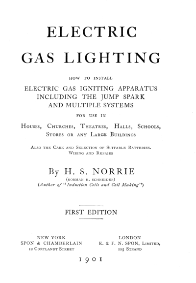
| Frontispiece—Complete Wiring Plan for a House. | ||
| 1 | Diagram of Simple Circuit | 2 |
| 2 | Diagram of Simple Circuit with Spiral | 2 |
| 3 | Diagram of Simple Circuit with Spiral and Galvanometer | 2 |
| 4 | Diagram of Circuit with Iron Core | 4 |
| 5 | Diagram of Ruhmkorff Coil | 4 |
| 6 | Elevation of Ruhmkorff Coil | 6 |
| 7 | Pendant Burner | 7 |
| 8 | Burner Circuit | 8 |
| 9 | Plain Burner | 10 |
| 10 | Ratchet Burner | 11 |
| 11 | Stiff-Pull Pendant | 12 |
| 12 | Stem Burner | 14 |
| 13 | Argand Burner | 15 |
| 14 | Welsbach Burner | 16 |
| 15 | Acetylene Burner | 17 |
| 16 | Push Button | 19 |
| 17 | Bartholdi Burner | 21 |
| 18 | Boston Automatic | 22 |
| 19 | Concealed Automatic | 24 |
| 20 | Diagram Wiring One “Automatic” from Two Pushes | 27 |
| 21 | Diagram Wiring One “Automatic” and Two Pendant Burners | 28 |
| 22 | Simple Switch Connections | 33 |
| 23 | Details of Automatic Connections | 35 |
| 24 | Details of Cellar Automatic Circuits | 35 |
| 25 | Nut Wrench | 40 |
| 26 | Automatic Operated by Door-Trip | 44 |
| 27 | Primary Coil | 46 |
| 28 | Syracuse Cut-Out | 50 |
| 29 | Boston Cut-Out | 51 |
| 30 | Details Cut-Out Rod—Normal | 52 |
| 31 | Details Cut-Out Rod—Operating | 53 |
| 32 | Bulb Cut-Out | 54 |
| 33 | Jump Spark Burner | 56 |
| 34 | Welsbach Burner for Series Lighting | 56 |
| 35 | Pillar Burner | 56 |
| 36 | Circuit For Jump Spark Gas Lighting | 57 |
| 37 | Insulator | 59 |
| 38 | Edwards’ Condenser | 60 |
| 39 | Edwards’ Burner | 61 |
| 40 | Edwards’ Burner | 61 |
| 41 | Diagram of Edwards’ Condenser Circuit | 62 |
| 42 | Circuit for Jump Spark Switch | 64 |
| 43 | Electromagnetic Trailer | 66 |
| 44 | Diagram of Ruhmkorff Coil Circuit | 68 |
| 45 | Windings of Sections | 73 |
| 46 | Sectional Diagram | 74 |
| 47 | Contact Breaker | 75 |
| 48 | Contact Key | 76 |
| 49 | Fall of Potential Diagram | 79 |
| 50 | Series Arrangement | 81 |
| 51 | Multiple Arrangement | 82 |
| 52 | Leclanche Cell | 84 |
| 53 | Samson Cell | 87 |
| 54 | New Standard Cell | 90 |
| 55 | Edison-Lalande Cell | 92 |
| 56 | Fuller Cell | 94 |
| 57 | Grenet Cell | 95 |
The enormous number of fires arising from the use of matches, and the great convenience and freedom from danger of the electric method of gas lighting, are alone sufficient reasons for the issue of these pages.
The veriest tyro in electrical operations knows that electricity will cause a spark, and most persons are aware that the spark possesses considerable deflagratory powers, varying with the character of the spark. In electric gas lighting a spark of the proper character is passed across a jet of gas and ignites it. Sparks can be produced by various means: friction, battery current, induction either galvanic or electro-magnetic, by a Wimshurst or Toepler Holtz machine, or an induction coil operated by a battery. For our purposes we will consider only the latter; the former are rarely used, being uncertain and unwieldy.
Of batteries there are many kinds, and although[Pg 2] all will produce sparks, yet for electric gas lighting those made for intermittent work and classed as open circuit cells are to be preferred. Open circuit batteries, which will be fully described in a subsequent chapter, include the Leclanche, and most of the so-called “dry” cells.
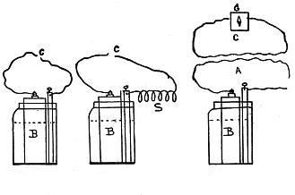
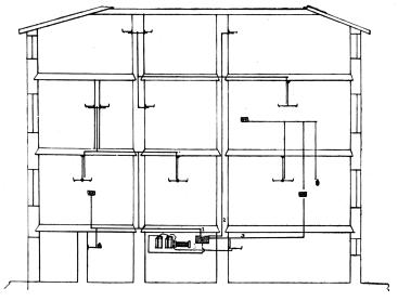
Fig. 1., Fig. 2., & Fig. 3.
If two wires be attached to a cell of battery B, one to the carbon or positive pole and the other to the zinc or negative pole, and their free ends be tapped together, minute sparks at C will be observed each time the wires separate (Fig. 1). If now a coil of insulated wire S be included in the circuit, Fig. 2, upon repeating the make and break of contact,[Pg 3] the sparks will be much increased. This arises from induction, each adjacent turn of wire acting upon its neighbor. To better understand the action of induction, we will consider the following examples: Fig. 3. A is a circuit in which is the battery cell B. C is a second circuit lying close to but well insulated from circuit A. G is a galvanometer in which a magnetized needle swings right or left each time a current is passed through a coil of wire encircling it. Now, although there is no battery cell in circuit C, yet the needle will swing each time the circuit A is closed or opened; that is, each time the wire ends are touched together or separated. This swing of course indicates that a current is passing through circuit C, but as there is no battery or other source of electrical energy included in it, it is clear that it arises from the action of the current in circuit A. In point of fact, the needle swings one way when the circuit is closed and the reverse way when it is opened; but the greater swing on opening the circuit indicates the greater strength of the induced current at the moment the current ceases to flow in circuit A. Note that these[Pg 4] current impulses are only momentary. In the case of our single coil, Fig. 2, each turn of wire acted upon itself in a similar manner to the circuit A upon circuit C.
Fig. 4., & Fig. 5.
An iron rod or bundle of iron wires, P, inserted in the coil, Fig. 4, but carefully insulated from it, will immensely increase the inductive effects and consequently the spark. This arrangement constitutes the simple primary coil used in pull-down or pendant and automatic burners. This spark is often a source of inconvenience; it appears wherever a circuit including similar coils is made and broken. In telegraph apparatus at key and relay contacts it is noticeable; in fact, the writer has used temporarily a pair of electro-magnets from a telegraph sounder and obtained[Pg 5] spark enough to operate a gas lighting burner.
To produce a long spark which will jump across an air gap, a more complicated form of coil is needed, one which more closely corresponds to the experiment noted in Fig. 3. The simple primary coil has here another coil of finer wire, S, wound on it but carefully insulated from it (Fig. 5). This second coil, or “secondary,” has a vast number of turns of fine wire as compared with the primary, which has only comparatively few turns of coarse wire. A primary coil of 40 feet of No. 14 B. & S. copper wire would be inserted in a secondary coil of perhaps 16,000 feet of No. 36 B. & S. This secondary coil, in fact all the apparatus constituting the induction coil, must be most highly insulated, as the electromotive force of the spark is tremendous, and it would be liable to pierce its way through and into the internal winding and so destroy the apparatus. The circuit in the primary is made and broken either by a hand key or by an automatic contact-breaker at C. With a large coil, the intensity of the spark at G is such that it will jump an air-gap of from one-eighth of an inch to over three feet.[A]
This combination of coils and contact-breaker is generally known as a Ruhmkorff or intensity coil, and is shown in elevation in Fig. 6.
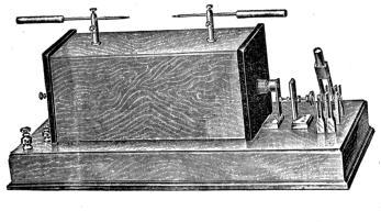
Fig. 6.
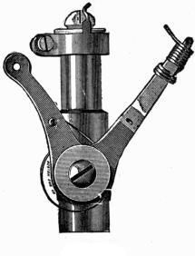
Fig. 7.
As we have already seen how a spark is exhibited at an interrupted contact, the means of its application to gas lighting will be considered. Fig. 7 represents the most generally used kind of electric gas burner or “pendant[Pg 8] burner.” Its application is shown in Fig. 8. The wire W from the coil C is attached to the brass insulated collar carrying the contact[Pg 9] S. The other wire from coil C and battery B is attached to the gas pipe G. As the burner is also screwed into the gas pipe itself, the circuit would be closed were it not for the gap at A on the burner, caused by the collar carrying the contact C and wire W, being insulated from the burner pillar P. When, however, a pull is given to the burner arm chain so as to cause the end of the spring R to strike contact C in passing, contact is made and broken, and a spark passes which ignites the gas issuing from the burner tip, the gas having previously been turned on. A piece of chain with a metal ball is attached to the burner arm in order to pull it down. In this class of burner there are many different makes differing only in minor details.
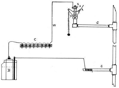
Fig. 8.
Fig. 9 shows a form of pendant burner which has no platinum contact, but has a broad lug on the insulated collar which is scraped against by the spiral spring when the arm is pulled down. It will be seen that the lug is not held by an insulated collar on the burner top, but is on the extension of an arm attached to the burner pillar by a large screw and insulating washers. The circuit wire goes under the smaller screw seen on the lower part[Pg 10] of the contact arm, this forming a strong and neat form of attachment.
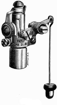
Fig. 9.
Now it has heretofore been necessary to turn on the gas before pulling the chain of a pendant burner, but as this is not always desirable the ratchet burner is made. Fig. 10 shows burner carrying a toothed wheel, which is partly rotated when the arm is pulled[Pg 11] down. This wheel is mounted on the stem of a valve which opens or shuts according to the point of rotation, and thus shuts off or admits the gas to flow up to the burner. One pull of the arm turns the gas on; at the same time the wipe spring touches the contact on burner collar, and the gas lights. A second pull and the wheel, rotating, turns off the gas.[Pg 12] In all burners of this class a spring is provided to carry the arm up and back into its original position ready for another pull. Some burners do not make contact when the arm flies back, thus saving battery current.
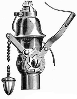
Fig. 10.
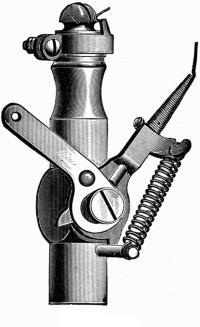
Fig. 11.
Fig. 11 is an improved form of burner wherein the movable electrode does not pass through the gas flame, neither do the electrodes come in contact with each other when the gas is[Pg 13] being turned off. Reference to the cut will show a pin protruding from the base of the coiled spring electrodes, which pin is so arranged as to come in contact with the short end of the pull-arm. When this pull-arm is pulled down it pushes up this pin, elongating the spiral spring electrode sufficiently to make and break contact at the fixed electrode on the burner collar. This burner can be fitted with a porcelain candle slip if desired to match the imitation candle burners.
Objection is sometimes made to the ordinary chain pulls from the fact that they jar the fixtures, and also are liable to bend the fixture branches from the strain used in operating the arm. To overcome these objections the stem style of burner is manufactured (see Fig. 12). This stem, it will be seen, carries a convenient key at the end, which is turned either right or left as in an ordinary gas-cock. The moving contact only makes contact when the gas is being turned on and lighted. When turning it off, the arm is retracted so as not[Pg 14] to touch the fixed electrode, thus saving battery current.
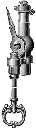
Fig. 12.
Fig. 13 is a simple lighting attachment for an Argand burner. The moving lever which carries the pull has a German silver spiral[Pg 15] spring on its top end. This strikes against the lug projecting from the circuit-wire arm and makes a spark. The lower part of the circuit-wire arm has a screw and washers for ready attachment, and is strongly and substantially made.
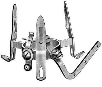
Fig. 13.
A means of igniting the gas from a Welsbach burner is shown in Fig. 14, and is so simple as to need no further explanation.
Owing to the deposits of carbon, it is necessary to construct burners for acetylene gas in a different and more substantial manner than those designed for coal gas.
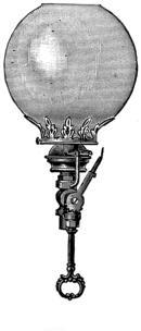
Fig. 14.
The best arrangement is depicted in Fig. 15, which has a pilot-tube burner as well as the two main tips. On turning the key, gas is admitted to both main and pilot burners, but[Pg 17] the electrode in breaking contact only ignites the gas at pilot burner, which, in its turn,[Pg 18] acts as a lighter for the main burner. Turning the main burner out, the pilot light can be left burning if desired, giving a small light, it being not feasible to turn down the main burner owing to the before-mentioned carbonization.
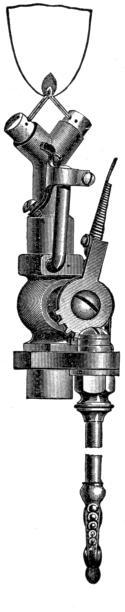
Fig. 15.
The orifice of an acetylene burner is much smaller than that of a coal gas burner, the former burning about one-half foot per hour, against six or seven feet of the latter.
The flame from this gas is hotter than that of coal gas, and deposits so much more carbon that a slight modification is necessary in the construction of burners for it. The details can be readily seen on observation of a burner, being simply in the adjustment of the contacts and their operation. It is better, however, to use a larger coil and a stronger battery for gasolene gas lighting than would be needed for coal gas—say, 6 cells of Samson, or large-size New Standard dry battery and a 10-inch coil having about 4 pounds or more of wire on it.
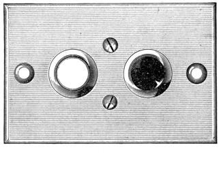
Fig. 16.
There are several forms of these burners, but the principle of all is the same. A gas burner protrudes from the top of a brass case which encloses the actuating mechanism. This mechanism consists generally of two electro-magnets, the armature of one opening the valve and allowing the gas to flow, at the same time vibrating a platinum-tipped rod against an electrode upon the burner collar. This produces a series of sparks at the burner tip which ignites the gas. A second magnet is provided which shuts the valve and extinguishes the gas. Some devices use one[Pg 20] electro-magnet to both open and close the valve, but the majority have double electro-magnets. The circuit is worked from a push button, Fig. 16, situated wherever desired; pressure on a white button lights the gas and on a black one shuts it off.
Instead of a rotating stop-cock, as in other automatics, a gravity valve is employed in the Bartholdi, which is held to its seat by the weight of the armature and connecting stem, as shown in figure 17. When the gas is turned off the valve rests upon its seat, as indicated in the cut. By a closure of the electric circuit at the turn-on button, two of the helices M P are energized, causing the armature J to be lifted, thus, by means of the stem H, raising the valve G from its seat into the dotted position, and opening the gas way so that the gas may issue to the tip, as shown by the arrows. At the same time, the top of the valve strikes against the end of the lever W, causing the circuit to be broken at the spark points T U, resulting in a continuous sparking as long as the finger[Pg 21] presses the button. The magnet when raising the armature has also twisted or partially revolved it, so as to bring the notch d in the armature over the end of the hook e, as shown in the dotted lines. When the circuit is broken by lifting the finger from the button, the notch falls into the hook and the valve is locked open.
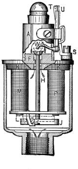
Fig. 17.
To extinguish the flame, the turn-off button is pressed, when a second magnet (not shown in cut) lifts the armature and twists it in the opposite direction, so that when the circuit is broken the armature falls free to its normal position, closing the valve.
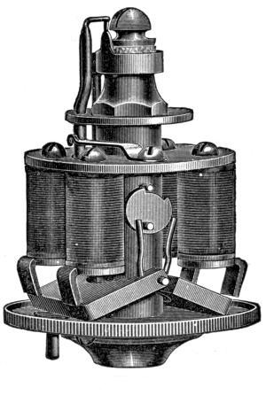
Fig. 18.
This automatic burner, Fig. 18, is typical of the class having two magnets, one to open[Pg 23] valve and light gas, and another to close valve and extinguish the light. It embodies an improvement over the older types of burners in that the binding posts are mounted on a rubber strip held by two screws, thus preventing the twisting and loosening so common heretofore. It also allows of the valve being opened and gas lighted by means of a match should the battery fail.
This is an automatic burner which has no valve mechanism, but ignites the gas only. It is generally placed in a cluster or ring where the burners are close enough to light by contagion. It is much smaller in diameter than the regular automatic burners, being but one and three-quarter inches in diameter.
Automatic burners are also made for Argand, but present no radical difference in construction over the regular type.
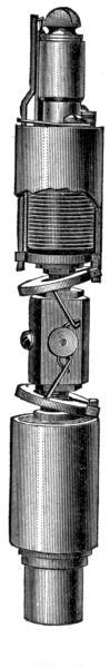
Fig. 19.
This automatic, Fig. 19, consists of two iron-clad magnets, placed one above the other, between which is located a gas valve. Through[Pg 25] an extension of the latter a pin is driven, one end acted upon by the upper armature to open the valve and ignite the gas, the other by the lower armature which serves to close the valve and extinguish the flame. Around the burner is placed a porcelain candle slip of 3/4-inch diameter and from 4-3/4 inches in length upwards.
Fig. 20 shows how to connect up an automatic burner with two pushes; thus one can be downstairs in the hall and the other upstairs, allowing one to either extinguish or light the gas from either place. The value of this arrangement is obvious; it allows one to light up the hall before descending at night, or to put out the gas after one is safely upstairs. Again, an automatic burner can be put in the cellar and lighted and extinguished from the head of the cellar-stairs, saving matches and danger of fire.
Fig. 21 shows the connections of one automatic burner and two pendant or rachet burners. P P are the pendent burners, A the automatic burner, C the primary coil, S the buttons which control the automatic burner, M M M the cells of battery, of which there should be at least four, if not six. A low-resistance cell must be used here, as before[Pg 27] mentioned, one that gives not less than 5 amperes on short circuit. It will be seen here that one side of the battery is connected to ground (or gas pipe), the circuit being com[Pg 28]pleted owing to the burners being themselves screwed into the gas pipe. Care must be taken, however, to first see that no insulating bushings have been used at the gas fixtures,[Pg 29] as is done in wiring for electric light. In this case a double circuit will have to be run.
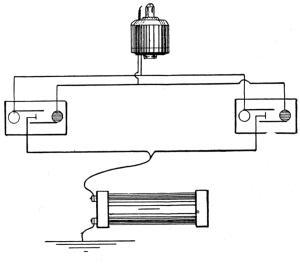
Fig. 20.
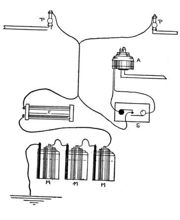
Fig. 21.
In wiring up an automatic burner with two electro-magnets, two wires are run, one from the black button and one from the white button on push-plate. Most burners have binding posts inside the case, the wires running through a rubber-bushed hole in the base. One of the greatest defects in the old style automatics arose from the two binding posts being fixed on a hard rubber block, which was held by one screw to the burner top. This screw got loose at times and the block used to twist, making it hard to tighten the wires. But improvements have been made in this direction, the later burners having a block with a projection which engages in a hole in the cover, and is held by two screws.
If the push has been set in place, and all wiring done, connect up the burner, first ascertaining to which binding post the two wires run. This is done by having one button pressed, the lighting (white) one, for example, and then touching the binding post with either wire. The lighting armature will buzz violently when touched, whereas the extinguishing one only strikes once when contact is[Pg 30] made. When only one person is working, a pin can be wedged in the push so as to keep the circuit closed.
In setting up these burners care must be taken not to bend contacts or alter adjustments, and absolute precaution is necessary that no wires touch where uninsulated. A cause of trouble is a dirty burner which does not allow the gas to strike the contact spark. The collar carrying the second contact may shift, or perhaps become short-circuited in a pendant or ratchet burner; a strip of asbestos will remedy this.
In fitting a house with electric lighting burners, the question of selection is best solved as follows: For the main hall and foot of the cellar-stairs, use the automatic burner. For other hallways, dining-room, drawing-room, and bathroom use ratchet burners which turn on and light gas when chain is pulled. For bedrooms use plain pendant burners; automatics and ratchets add an element of danger, in that they may not turn off gas, or may leak. Most of this type on the market are as reliable[Pg 31] as it is possible to make them, but still accidents will happen.
The frontispiece shows a diagram of the wiring in a dwelling house of medium size, dividing it into three sections, each section being controlled by a switch—either a hand switch or one of the automatic cut-out switches elsewhere described. The burners are distributed as follows:
No. 1 in the front cellar, pendant or ratchet.
No. 2 in the rear cellar at foot of stairway is an automatic burner controlled from kitchen above.
Nos. 3 and 4 ratchet burners on chandeliers in drawing-room and dining-room.
No. 5 ratchet or pendant in kitchen.
No. 6 pendant in bedroom.
No. 7 ratchet or pendant in bathroom.
No. 8 pendant in bedroom.
No. 9 pendant in bedroom.
Nos. 10, 11, and 12 pendants in bedroom.
No. 13 automatic burner in hallway operated from pushes in lower and in upper hallways.
The articles required for this job are as follows:
Two automatic burners.
Three gas lighting push-buttons and bases. Pendant and ratchet burners according to number of lights in rooms.
Six cells—open circuit battery.
One three-lever switch.
One 8 or 10 inch spark coil.
Three pounds No. 16 patent finish office wire.
Two ounces No. 24 gas-fixture wire.
One pound tinned 3/8" staples.
Few square inches tinfoil.
Small roll insulating tape.
Tools: 4-inch screwdriver, pocket knife, 4-1/2-inch side-cutting pliers, hammer, piece of sandpaper.
The simple section switch is shown enlarged in Fig. 22. The wires 1, 2, and 3 are from their respective circuits and terminate at the switch arms A A A. The wire from the battery B and coil C runs to each switch-stud S S S. If trouble shows on the line, each circuit can be thrown off by moving its switch arm until the fault is located. If it is not found at once, and the battery is weak, (test each cell with an ordinary electric bell), open all the circuits until the battery is recuperated,[Pg 33] and disconnect the battery wire from the switch. Then attach the battery wire to the bell and touch each switch lever with a wire from the other binding post of the bell. If there is a short circuit on any section, the bell will ring or tremble when the arm is touched.
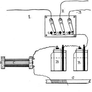
Fig. 22.
On the contrary, if the burners fail to work and no sign of a short circuit can be thus[Pg 34] obtained, it is evident that a wire is broken or a screw is loose.
To locate a break, connect up the bell as just described and attach the testing wire to the switch with all levers closed; this is actually putting the bell in series with the battery, coil, and ground. Then hunt for the break. Take a long piece of wire and fasten one end to a ground pipe. Then touch the other end to the circuit wire in the cellar as far as you can go, baring the insulation in spots, but carefully re-insulating it again. If there is no break in the cellar, the bell will ring loudly at each contact. Next, proceed to the next floor and repeat the operation, gradually working away from the battery. As soon as you pass the break, the bell will fail to respond. Two persons here are better than one, as it may be necessary to go quite a distance from the bell before finding the trouble.
Fig. 23 shows details of the wiring from
the hall light to the two push-buttons. A wire
is run right down from the top push T, middle
connection, past the lower push L, where a
similar branch joins it, until it reaches the
section switch. The lighting and extinguishing
wires from the lower push run up and are
[Pg 35]
[Pg 36]joined on to the similar wires from the top
push, which latter wires go directly through
the floor and ceiling to the automatic burner A.
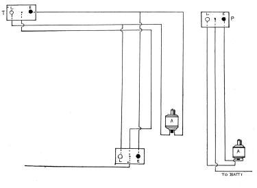
Fig. 23., & Fig. 24.
Fig. 24 is the detail of the wiring for the cellar automatic burner A, from the push P, and is so clearly shown as not to require further explanation.
The secret of success in gas-lighting work is careful wiring. The platinum tip of the vibrating rod is often bent, either by accidental blow or by the continual hammering against the tip on the collar. This often causes an open circuit when the lighting armature refuses to buzz. Again, soot will form, causing weak action owing to imperfect contact. Examine, adjust, and clean; here, as in all electrical work, contacts must be clean.
In general wiring, use weatherproof office wire, or, better still, well-made electric light wire. For ordinary house work No. 16 B. & S. gauge is preferable; smaller wire means higher resistance and less current at burner. For braided office wire, No. 16 runs about 95 feet to the pound, No. 18 about 135 feet to the pound. The cheaper grades of wire without the patent finish or extra insulation are not worth using; sooner or later trouble will ensue,[Pg 37] and once a house is wired, it is no pleasant job to hunt trouble, especially if the wire was put on before the plaster. In modern buildings in large cities, the use of conduit tubes has become general, but the handling of these conduits comes more under the province of the electric-light wireman and less within the scope of these pages.
In wiring new wooden buildings do not draw wires too tight; the wood may expand and either break wire or cause a weakening of the insulation. In wiring before the plaster is put on, always leave a good length free, so it will not be covered up by the plasterers.
The wire used on the gas fixture is of a special kind, being made for the purpose. It is made in two sizes, No. 22 and No. 24 B. & S. gauge, and with three windings of cotton, three outer layers of cotton and one of silk, or three windings of cotton which is soaked in fireproof preparation, and then wound with silk.
As the piece used is generally short, these small sizes are sufficient in carrying capacity. After wiring up a fixture, this fine wire can be tied on to the pipes, etc., with thread, and a good coating or two of shellac varnish applied.[Pg 38] When this is dry, the thread can be removed and the shellac will hold the wires on to the fixture. On no account finally connect up the battery to a circuit when shellacking the wire. Wait until the shellac is thoroughly dry and hard—at least half a day, if possible.
White lead is generally used at the joints where the burner screws into the fixture, but tinfoil wrapped round the joint will give good service. It prevents leaks and ensures a good contact.
The ground connection at the battery must be first-class; do not be content with just wrapping a few turns of wire around the pipe in the cellar (assuming the battery is in the cellar), but clean and scrape the pipe; clean at least two feet of the wire, wind it tightly and evenly on the pipe and solder it. There is a pipe-clamp made which is clamped on the pipe and the wire attached to that, but it must be properly put on a clean surface.
In wiring finished houses, especially wooden ones, the wires can be run along skirting boards, and often pushed out of sight in the[Pg 39] space between the floor and the skirting. This is quite permissible, as the wires, unlike electric-light wires, carry no dangerous current; but waterproof wire becomes preferable, as the water used in washing a floor will often creep under and rot the insulation. In going upstairs, wires can often be run in the fluting of a moulding along the stairway, and be quite inconspicuous; but wherever possible, fish the wires up inside the wall. The main thing to be considered in wiring is that the wires are large enough, well insulated, all joints well made and taped and put where there is no danger of injury. Rats have a habit of gnawing paraffin-coated insulation, and it is well to run such in metal tubes. In joining or splicing wires, do it in a thorough manner, and solder if possible. Never use the old bell-hanger joint—the one in which the ends of the wires are merely looped together. Strip insulation and scrape or sand-paper bright about three inches of each wire to be spliced. Then, placing the bare wires across each other about three-quarters of an inch from the insulation, tightly wind the loose bare ends of each around the bare inside portion of the one it is being spliced to. A touch of solder will prevent trouble from oxidation, after the[Pg 40] adhesive tape has been wrapped on. Attention to details like these will often ensure the satisfactory working of the job.
A handy tool for gas-lighting wiring is shown in Fig. 25. One end is bored out to fit the small nuts on the ratchet and pendant burners, and the other is filed flat for use as a screw-driver.
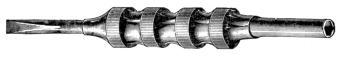
Fig. 25.
A case may arise where there is electric light on the same chandelier as the gas lights, and that an insulating bushing has been screwed in between the fixture and the pipe. In this case it will be necessary to run two wires to each burner, the pipe common return being now unavailable. Another scheme is to interpose an insulating bushing under each burner; then the second or return wire need only be run from the burner to the gas pipe outside the main bushing. But the local fire-insurance rules must first be consulted.
Most ceiling gas fixtures will admit of the fixture wire being run inside the brass shell,[Pg 41] which makes a neater job. But the very best of insulation must be used, and great care be taken that it be not abraded. It should be shellacked or otherwise insulated before use. The electric-light fixture wires are admirable for use here if there is room.
For concealed work in a finished house, locate the position of the fixture under the floor of the room above by measuring both in the room where the fixture is and in the room above. Then cut out a piece of the floor, drill up from underneath through the fixture plaster-rose with a fine drill, and push the fixture wire up. The main wire can be laid under the carpet, or along the floor-crack in the upstairs room.
In wiring up wall-fixtures, push-buttons, etc., it is often possible to fish the wire up from the floor by punching a hole at the fixture and inserting a piece of chain (made for the purpose), attached to a long and stout thread. Then drill into the skirting near the floor plumb underneath the first hole and fish for the chain with a piece of wire having a hook on the end of it. Where fixtures have brass rosettes, these can be removed by (generally) unscrewing the fixture, but first shut off the[Pg 42] gas at the meter, or plug the hole; this may seem unnecessary advice, but experience warrants its being given. When the chain is fished out, a piece of wire can be attached to the thread and pulled through in turn. In most cases its point of exit at the fixture can be concealed by the rosette, through a hole in which it passes. Take care that the edges of this hole do not cut the insulation. Care must be taken at every step in gas-lighting wiring.
In wiring up a push-button, screw all wires tightly under their respective binding screws, and then cover wherever possible with adhesive tape. As the wires must be somewhat loose to allow of the connections being made at the back of the push-button at the wall, they will have to be carefully pushed into the hole, and if they are not tightly held by screws, trouble will result. It is a good plan, when using fine enough wire, to make a sort of eye at the end of the wire and pass the screw through this, instead of merely giving the wire end a turn around the screw and then driving the screw home. Of course washers should be used wherever an ordinary screw holds a bare wire.
One of the uses to which an automatic burner can be put is in conjunction with an electric door-spring, lighting when the door is opened, but preferably extinguished by independent push. In this case, a form of trip spring should be used which would only make contact during a portion of the travel of door. Such a trip is shown in Fig. 26.
A is automatic burner; C, the primary coil; B, the battery; T, a swinging trip piece of brass hinged in brass plate, P, which is screwed over the door in such manner that the door opening in direction of the arrow will cause the trip T to strike against the spring S, and make contact. This spring is insulated from the plate P by the hard rubber block R.
On the door being opened, the trip will make
contact long enough to light the burner and
will then fall back as the door passes. On
shutting the door, the trip will be raised and
will fall as the door passes, but will not make
contact. Or, if so desired, it can be made to
operate a second contact to extinguish the
burner by fixing a second insulated spring so
it will be pressed when the top of trip makes a
[Pg 44]
[Pg 45]downward movement—as when the door
passes it in shutting.
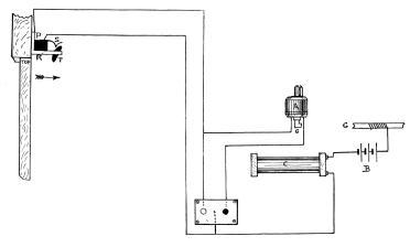
Fig. 26.
Various applications of automatic burners in connection with burglar alarms will suggest themselves, but in these cases the utmost care must be taken that the apparatus is in good working order; failure to light might cause the room to be filled with gas, and serious results ensue.
For those persons who use gas stoves and are mechanically inclined, an arrangement of an alarm clock with an automatic burner will enable them to light up without getting out of bed, or perhaps even waking up.
To construct a primary coil such as used with pendant or automatic burners presents no difficulty. The most convenient sizes are those 8 to 10 inches in length and about 3 inches in diameter. It is quite common to speak of these coils as 8 or 10 inch coils; to the writer’s knowledge this has been taken to mean a Ruhmkorff or double-wound induction coil, giving a free 8 or 10 inch spark.
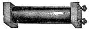
Fig. 27.
To make such a coil (Fig. 27), proceed as follows: Prepare a spool by gluing a paper or fibre tube 3/4 inch in outside diameter by about 1-16 inch thick into square or round[Pg 47] spool ends three inches square, one-half inch thick, and having each a centre hole just large enough to admit of the tube being held tightly. These ends should be firmly fixed on the tube; a pin or two driven through tube into end will assist in strengthening the joint. Now wind on the tube about 3 pounds No. 12 B. & S. cotton-covered magnet wire. This will give about six layers of 80 turns each, nearly 500 turns in all, a total length of, say, 150 feet, measuring .25 ohm. The ends of the wire are to be brought out through holes drilled in the spool ends, and can be fixed to brass binding posts on those ends.
Into the paper tube push as many iron wires 8 inches long by No. 22 B. W. gauge as will fill it. These iron wires can be tightened finally by driving in at each end, a stout wire nail.
Although not absolutely necessary, a coat or two of shellac varnish applied to the windings will make a better insulation. Shellac varnish is readily made by dissolving one part gum shellac in four parts of alcohol. For coils which are likely to be in damp places, a good saturation with insulating compound, such as P. & B. paint, will render them waterproof.[Pg 48] The need for good insulation in these primary coils is not so urgent as in Ruhmkorff coils, owing to the lower potential of the current.
A smaller coil can be made with No. 14 B. & S. wire where the battery is of higher resistance (or gives less than ten amperes on short circuit). The remarks on battery selection on another page will be found to meet application here.
Where there are a number of burners to be installed in different parts of a house, it becomes desirable to wire in a number of circuits. As one end of the circuit is already grounded, a second ground will cause material injury to the battery if not detected in time. It becomes, therefore, necessary to be able to open a grounded circuit without affecting all the lights in a house. This is possible with the multiple circuit arrangement by using a switch, either automatic or operated by hand.
The simplest form of danger signal is the relay electric bell attachment, which device is mounted on the end of the gas-lighting coil.[Pg 49] It consists of an armature which closes a circuit when attracted by the coil core, in which circuit are included a battery and electric bell.
Now when an ordinary pendant or ratchet burner is pulled, it only sends a momentary current through the coil, enough to magnetize the core, but not enough to attract the armature sufficiently long for the bell to ring. But if a short circuit or ground should occur, the armature is held against the contact long enough to cause the bell to ring and give warning. In some cases a constant ringing attachment is added, in which case the bell rings until some one stops it.
This is a most ingenious device for opening a short circuit, depending on its action upon the sluggish movement of glycerine (Fig. 28).
A sealed glass tube pivoted near its centre contains a portion of glycerine sufficient to considerably overbalance it and keep one end down. A soft iron armature is attached to this tube in such manner that each time a current flows through a pair of electro-magnets, the attraction of the armature causes[Pg 50] the tube to tilt and the glycerine flows along to the other end. Now it will be readily seen that if the tube is only tilted for a second or so, the slow-moving glycerine will not have flowed sufficiently to the end to overbalance it, but it requires an attraction of the armature for a considerable period. This electro-magnet is in circuit with the gas-lighting wires, the tube being provided with contacts in such manner that, when fully tilted, the circuit is broken. The momentary jerks imparted to the armature by the operation of a pendant or automatic burner will not be enough to permanently tilt the tube and break[Pg 51] contact, but a short circuit will hold the armature tight down, until the increasing weight of glycerine causes the tube to open the circuit.
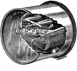
Fig. 28.
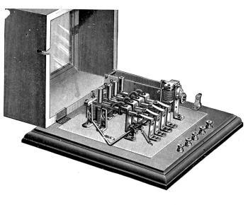
Fig. 29.
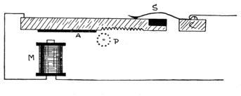
Fig. 30.
This cut-out, Fig. 29, is representative of the class which use clockwork, and is both simple and reliable. The house circuit is in series with an electro-magnet which controls a clockwork having a long pinion shaft. This clockwork starts and runs while the house circuit is closed, as on operating a burner, but stops when the circuit is opened and flow of current ceases. The wires leading to different circuits in the building run through a number of contact springs mounted on sliding rods, which have teeth cut on the under side (Fig. 30). These rods have soft iron armatures on the opposite ends from the contact springs, which rest over electro-magnets, also connected to the house circuits. When the clockwork starts, the pinion shaft revolves, but does not engage in any of the sliding rods, as[Pg 53] they just clear it. Should a heavy or continuous current pass through one of the electro-magnets, it attracts the armature on the corresponding rod (Fig. 31), and the turning pinion engages in the teeth, drawing up the rod and breaking contact.
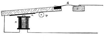
Fig. 31.
Fig. 32 is a form of battery protector which works on the gravity principle. Here each section is governed by a rocking contact, operated by two glass bulbs partially filled with a volatile fluid (such as ether), and joined by a glass tube. In one of these bulbs is a platinum wire which is included in the circuit and heats upon the passage of a strong or continuous current. If the circuit is closed too long, the heating of the platinum wire causes the fluid to flow into the upper bulb, and, as the bulbs are pivoted, the increased weight of the upper bulb now overbalances the rocker and breaks the circuit on that section.
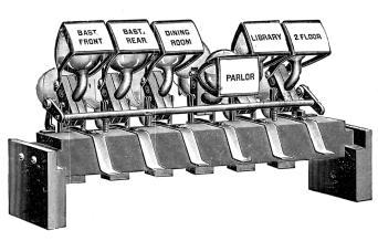
Fig. 32.
The jump spark system is used where it is desired to light clusters of gas jets situated in inaccessible places, or a number of them simultaneously. The spark from a Ruhmkorff coil, being made by a contact broken at the coil and not at the burner, can be divided up among a number of simple burners placed in series. One of the burners used and known as the Smith jump spark burner is shown in Fig. 33. The wires from the coil are attached to the electrodes shown on each side of the burner, and the spark jumps across the gap, situated nearly over the burner orifice. There is a guard-flange of mica round the lower part.
Fig. 34 shows the manner in which the jump spark is applied to a Welsbach burner. A small porcelain clip carrying the spark-gap wires is held on the top of the burner chimney. The electrodes project down into the chimney[Pg 56] so that a draught of air cannot carry the stream of gas away from the spark-gap.
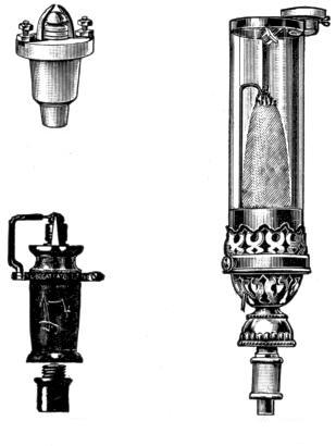
Fig. 33., Fig. 34. & Fig. 35
Fig. 35 shows a burner intended for the stage of a theatre, or where the lights are located in dangerous and inaccessible places. The burner is made of porcelain upon which are spun the metal top and bottom. One[Pg 57] electrode is also clamped around it, allowing of adjustment and better insulation.
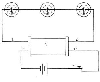
Fig. 36.
These burners are used in series, as shown in Fig. 36. B B B are the burners; S S, the secondary wires from the Ruhmkorff coil, I; P P, the primary coil wires from battery, opened and closed by means of the key, K.
It is often possible to place plain burners close enough so that they can ignite by contagion. In this case one of the plain burners[Pg 58] is removed and replaced by a multiple burner, as above.
It is customary to allow sixteen burners to one inch of spark, in which case the spark gaps are adjusted about one-sixteenth of an inch apart. A coil giving a 2-inch spark would operate 32 burners, but actually it would be found preferable to omit a few, so as to make allowance for any slight leak. A spark of over 2 inches is hard to handle, although often used; it is better to make up a number of circuits of, say, 30 burners each, and operate them alternately by a suitable switch.
The wire used to connect the burners is generally bare, although an insulated wire is sometimes used. But the electromotive force of a 2-inch spark is so high that it is better to run the wires so they do not come near anything liable to cause a leak. The remarkable tendency of these high-tension currents must be most carefully guarded against; indeed, it is what makes this style of gas lighting so often unsuccessful. A damp wall, gilt wall-paper, a gas pipe hidden in the plaster, will often lead off the current. The wires should be at least 50 per cent. further off[Pg 59] from any object than the spark length; that is, a 2-inch spark circuit should be at least 3 inches away from a wall, and the further the better. It cannot be too strongly urged that every precaution be taken to keep the wires away from objects other than their insulators.
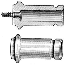
Fig. 37.
Fig. 37 shows the special form of insulator used. It is made of the highest grade glaze filled porcelain, and the screw is passed into it and holds against the lower end as far away from the wire as possible.
Glass tubes should be passed over the wires[Pg 60] wherever they come near any metallic object, that is, within sparking distance.
This system differs from the foregoing in that the spark-gaps are connected in multiple, instead of series, and each burner is provided with a small but efficient condenser.
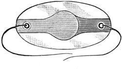
Fig. 38.
It prevents trouble should a wire break between burners, in which event only one burner would be out of commission, whereas in the first method, the whole number in that series would suffer. It is also more sure in action and presents less liability of the spark jumping to the ground. The burner pillars need not be made of porcelain or lava; in fact, the electrodes can be readily attached to the existing burner. Fig. 38 is a condenser consisting[Pg 61] of a small oval piece of mica, on each side of which is fastened, with insulating varnish, a spatula-shaped piece of tinfoil. One foil sheet is attached to the line, the other to the burner electrode. These condensers must not be allowed to get wet or their efficiency will be impaired.
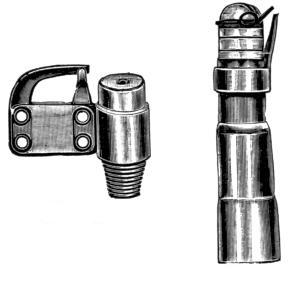
Fig. 39. & Fig. 40
Figs. 39 and 40 are the most generally used burners, the wire from the condenser being attached to the lug or top electrode, which is insulated from the burner by means of the mica plate to which it is riveted. The burner pillars are of course grounded through their[Pg 62] being screwed into the gas pipe. The circuit is shown in Fig. 41. I is the induction or Ruhmkorff coil, in the primary circuit of which is the key, K, controlling the current from the battery, B, and across which is bridged the[Pg 63] condenser, C C. When the coil vibrator is used, the condenser C C can be omitted, that of the coil itself serving instead. S is the wire leading from the secondary terminal of the coil to the burner condenser, C, which, in turn, are connected to the electrodes on the burners, P P, as before noted. The other secondary wire is grounded preferably to the gas pipe itself.
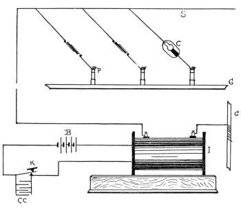
Fig. 41.
Where a lot of burners are placed together, as in a ring, it is often feasible to light them by contagion, one tip only being connected to the coil circuit, the others lighting from it and conveying the flame around to the rest. This avoids multiplicity of circuits, or, perhaps, too many burner gaps on one circuit; but the one burner may fail to light, whereas, where all are fitted, the chances of failure are less, especially in the Edwards condenser system.
In a switch for controlling the current of
the secondary coil it will be evident that the
utmost attention must be paid to matters of
insulation. The object of such a switch is to
control a number of circuits; for example,
[Pg 64]
[Pg 65]as it is not advisable to put more than 20 to 25
burners on one circuit, a case requiring the
lighting of 100 burners would necessitate some
means of passing the current to each circuit in
turn. This is shown in Fig. 42, in which S
is a hard rubber plate, provided with a revolving
metal arm and handle, H, and four
contact points, P, which latter receive the ends
of the wires from the groups of burner condensers
B by means of nuts or binding posts.
The wire from the secondary of the coil is
run to the switch-handle, H, great care being
taken that it does not pass near to the circuit
wires, or contact points. Revolving the
switch-handle connects the secondary wire to
each circuit in turn. It will be noticed that,
unlike a battery switch, this one has a large
base, long switch-arm, contact points situated
far apart, and every precaution taken to control
the passage of the high-tension current.
The base should always be of rubber or
glass. Shellacked-wood, or such substitutes,
are productive of trouble.
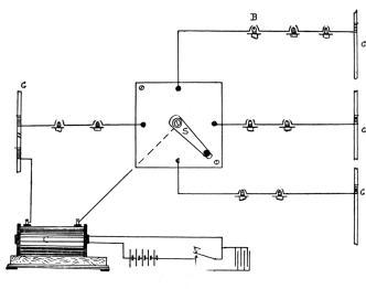
Fig. 42.
When it is desired to light automatically a number of burners from a distance, the Trailer (Fig. 43), is used. This is a switch similar to above, but the arm is revolved[Pg 66] by means of toothed wheels by the electro-magnet shown on the back. As it is never desirable to unnecessarily prolong the secondary wires, this device admits of the switch being put near the circuits, and yet being operated from afar.
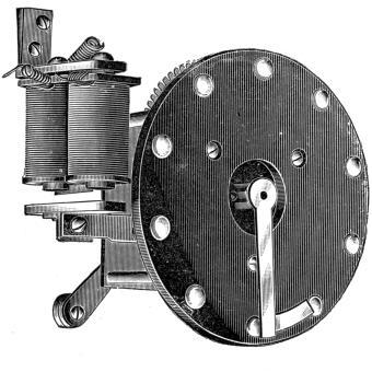
Fig. 43.
Fig. 44 shows a diagram of a Ruhmkorff coil, the letters referring as follows:
C the iron core, P the primary coil wires, I the insulating tube between primary P and the secondary coil S. In small coils this may be dispensed with, and a heavy layer of paraffin wax laid over the primary coil. D D are the ends of the secondary, showing sparking taking place between a pair of balls (or between the electrodes of a gas burner); R is a stiff spring fastened to the coil base and carrying a soft iron hammer, which is attracted toward the iron core, C, when current passes through the primary coil and magnetizes it. L is a battery, J, a condenser, to be more fully described later on. When the spring R touches the adjustment screw A at B, as they are insulated from each other, contact is made and reference to circuit will show that the current from battery L flows through primary coil, magnetizing the core and attracting soft iron hammer on R. As this bends forward, it breaks contact at B, the core loses its magnetism and the spring flies[Pg 68] back, to again make contact. This is repeated many times per second.
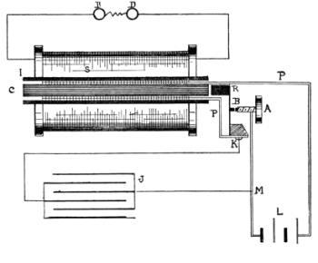
Fig. 44.
As a heavy spark occurs at B on the break of contact, the condenser, J, is attached at[Pg 69] M K. This is a series of insulated tinfoil sheets, which has the property of nullifying the spark at B, and so preventing the waste of platinum with which both adjustment screw A and spring R are equipped.
A Ruhmkorff coil differs from a simple primary coil in three main points. Two separate coils instead of one; high insulation, and a primary coil of few turns. In the simple coil we desired self-induction; here, we desire to avoid it as much as possible.
The average size Ruhmkorff coil, for jump spark work, would be one giving a 2-inch spark, specifications for which are as follows:
Spool—Nine inches long by one inch in diameter. End cheeks 4 inches high by 3 inches wide.
Core—Sufficient soft iron wires, 9 inches long by No. 22 B. W. gauge as will fill the spool tube.
Primary—Two layers No. 14 B. & S. gauge cotton-covered copper wire.
Secondary—Two and one-half pounds No. 36 B. & S. gauge double cotton or silk-covered magnet wire wound in four sections (or more than four sections, if feasible).
Condenser—Seventy sheets tinfoil 4 by 7-1/2[Pg 70] inches; 80 sheets condenser paper 5 by 8 inches.
This should be made up of a fibre tube 9 inches in length by about 1/16 inch thick, and should be firmly fixed into the spool ends. If it be glued in it should also be pinned as well; it is easily possible to drive in a few screws passing through the tube into the spool ends, particularly as the soft iron core, being of loose wires, will adapt itself to the slightly projecting screw-heads. Remember that this spool must be made strong; if it comes apart during the winding process, much trouble will ensue, and perhaps all the wires lost or ruined. For reasons to be seen later, do not affix the right-hand spool end yet, but have it ready. The core consists of as many fine iron wires, say of No. 22 B. W. gauge, as can be forced into the tube, but the core can better be added after the windings are all in; that is, in such cases where a rigid spool tube is used.
This consists of two layers of No. 14 B. & S.[Pg 71] gauge cotton (or silk) covered copper magnet wire, and should be evenly and tightly laid on. For winding coils, a lathe is a most handy machine, or the spool can be mounted on a spindle and rotated by hand. It is not feasible here to give all details of coil-construction; reference should be made to the many excellent works on the subject. The two ends are brought out through holes in the spool ends, as indicated for the simple primary coil before described. After winding, the wire is to be well basted with melted paraffin wax until it is saturated, any excess being scraped off so as to leave a smooth cylindrical surface for the secondary coil. Half a dozen turns of stout paper or oiled silk is now to be wound on, and enough paraffin wax added to leave an insulation at least one-quarter of an inch around the outside of the winding. The right-hand end of spool, where the end was not attached, will require a little care that the wire does not run off; but, as only two layers are to be wound, it is an easy thing to do.
When the primary coil is finished off, cut three pieces of hard rubber four inches square, with a central hole just big enough that they[Pg 72] may be slipped on over the primary coil to form divisions into which the secondary wire goes. These can be fixed equal distances apart by means of removable wooden blocks, which are taken off as each section is wound.
The secondary coil consists of about 2-1/2 pounds No. 36 B. & S. gauge silk or cotton-covered magnet wire, wound evenly in layers in the sections on the primary coil. Before any wire goes into a section, it must be seen that the division fits tight to the primary coil. It will be best to pour around the coil some melted paraffin wax so as to form an insulating ring, and prevent any possibility of the spark creeping under the section division into the next. The actual operation of winding presents no difficulty other than those of keeping the wire from damage and getting as even layers as possible. If each layer is separated from its neighbor by a strip of paraffined paper, it makes even winding easier, and better insulation. As to the insulating of the secondary coil, it can be done in a variety of ways. The coil can be soaked in molten[Pg 73] paraffin until saturated, or the wire can be made to pass through a dish of molten paraffin while on its way from the wire reel to the coil. In the latter case the wire must be guided by means of glass rollers, as the wax would harden rapidly if touched by the fingers. In connecting up the sections, the similar ends are to be joined; that is, the inside ends to inside ends, and outside ends to outside ends, as per diagram (Fig. 45). This will bring two outside ends free for attachment to binding posts. Fig. 46 shows direction of winding and connecting the two middle coils, A C being the inside layers next to primary and B D the outside layers.
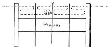
Fig. 45.
An outside coat of paraffin wax is now given to the coil and a wrapping of waxed[Pg 74] paper laid on. Then, if desired, a cover of sheet-rubber or a layer of cloth can be put on over all, to finish the job.
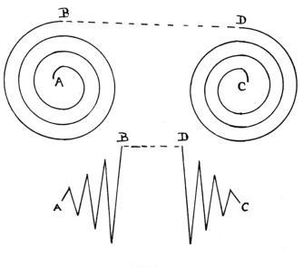
Fig. 46.
The base for a Ruhmkorff coil generally resembles an oblong shallow box. The coil is mounted on the lid, and the condenser inside the box, the connections being made on the lower side of the lid. It is preferable, except for appearance’ sake, to make all connections[Pg 75] outside the box, but this is left to the worker’s choice.
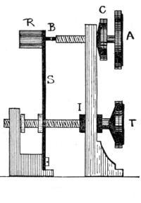
Fig. 47.
The Condenser is made up of 70 sheets of tinfoil each about 4 inches by 7-1/2, and 80 sheets of clean white paper 5 by 8 inches placed alternately, and saturated with paraffin wax. The tinfoil sheets are laid so that about 1/2 inch projects out of the paper sheets at each end, the alternate sheets coming out at the same end, and the projecting pieces being bent together gives the effect of a pair of tinfoil sheets insulated from each other, aggregating the sum of all the small ones.
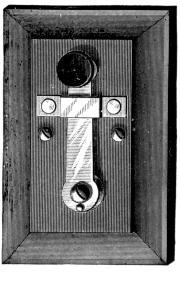
Fig. 48.
The coil can now be attached to the base by means of screws passing through the lid into the coil ends. If a vibrating contact breaker be desired, reference to Fig. 44 will show method of connection. Fig. 47 shows details of a contact breaker of similar design. R is hammer head of soft iron, S a spring about thickness of clock spring and 3/8 inch wide or more. B is contact point, both spring and adjustment screw A being fitted with platinum contacts. C is a check nut, to hold A from turning. I is an adjustment to tighten or[Pg 77] loosen spring S, by means of a lug which it carries on its shaft. It is well insulated from pillar carrying A, by the hard rubber bushing, I.
The condenser is laid in the box under the coil and attached as in Fig. 44; that is, one set of sheets to the contact pillar, and the other set to the adjustment screw.
For gas-lighting work, it is generally preferable to use a contact or strap key (Fig. 48), instead of a vibrator. The key can be mounted on coil base, in which case the condenser will be attached in same manner as for the vibrator.
Before entering into a description of the various batteries used in electric gas lighting, it will be well to briefly consider a few simple electrical rules bearing upon the subject.
A current of electricity has electromotive force, or difference of potential figured in volts, and current figured in amperes.
For example we will use the water analogy (Fig. 49). Two tanks, A B, on the same level, are connected by a pipe C.
Supposing tank A be filled with water and the pipe, C, to be opened; the water will flow along C into B until the level in each tank is equal. So long as there is a difference of level, there will be a pressure in C, owing to the water behind it.
Replacing the tanks A and B by unequally electrified bodies, and the pipe C by a conductor of electricity, the flow of water is represented[Pg 79] by the tendency of the electrified bodies to equalize themselves by a flow of current along the conductor, C.
To sum up: The difference of level is now difference of potential, the pounds pressure along the pipe being expressed as electromotive force in volts.
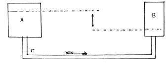
Fig. 49.
The quantity of water flowing along the pipe is measured, as electricity, in amperes. As the quantity of water passing in a given time is regulated by the size of the pipe and its own pressure, so the quantity of electricity is also regulated. A conductor of electricity offers resistance to the flow of current according to its sectional area and the material of which it is composed, this resistance being expressed in ohms. The greater the voltage and lower the resistance, the more current. This[Pg 80] law, and its kindred applications, are expressed as follows:
C = E/R.
C is current in amperes, E electromotive force in volts, and R resistance in ohms.
Thus a wire with a resistance of 50 ohms would pass 2 amperes with an electromotive force of 100 volts. To find resistance when other two factors are known, the formula is
R = E/C.
In selecting a battery for work, regard must be made to the current required, and its period of flow. For energizing a gas lighting primary coil, the current must be large, but is only required occasionally, the battery standing idle for long periods. In this case the class called open circuit cells are preferable, as they contain no strong acids and do not deteriorate to any extent when not in use. Of such class is the Leclanche-Samson, Monarch, carbon cylinder, and most so-called dry cells. As the resistance in a conductor[Pg 81] affects the current flow, so it does in a battery cell; the internal resistance of a battery is determined by its size, proximity of the elements, etc. Cells with small zincs and porous cups are of high internal resistance, those with large sheet zincs and big carbon surfaces, of low internal resistance. As the primary coil used in gas lighting is never much over one ohm, a cell of low internal resistance should be selected. But as the wires leading to the burners must be taken into account, a number of cells should be used to produce enough electromotive force to overcome the added resistance. Now battery cells can be arranged in a variety of ways—in series for higher electromotive force, and in multiple—for greater current.
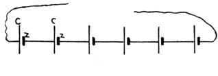
Fig. 50.
Fig. 50 represents the series arrangement; here the zinc of one cell is connected to the carbon of the next; this adds the electromotive[Pg 82] forces together and thus gives greater ability to overcome resistance, but it also adds together the resistance of each cell. Thus 4 cells, each 2 volts and of one-half ohm internal resistance, would, in series, have an E. M. F. of 8 volts and an internal resistance of 2 ohms, current 4 amperes. Fig. 51 shows four cells in multiple, the zinc of each cell and the carbons of each cell are connected. Here the result would be but 2 volts, but the internal resistance would be only one-quarter, viz: one-eighth of an ohm, current 16 amperes.
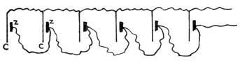
Fig. 51.
The readiest rule for connecting a battery is to arrange it according to the resistance of the line or outside wiring. So as we will have to use house-wiring far exceeding in length that on the coil, and probably of less diameter. Therefore the series arrangement will be the one to use, and not less than four cells of a low-resistance battery.
This battery consists of a carbon rod surrounded by granular peroxide of manganese forming the positive pole and a piece of zinc for the negative pole, both elements being immersed in a solution of sal ammoniac (chloride of ammonia). If a wire be run outside the solution and connecting the carbon and zinc, a current of electricity flows along it. The chemical action taking place is as follows: The zinc combines with the chlorine of the solution, liberating free hydrogen and ammonia. The hydrogen appears at the carbon, where it is acted upon by the oxygen of the peroxide of manganese. If too much current is taken from the cell, that is, if the wire or circuit be of too low resistance, the oxidizing action of the peroxide is not rapid enough, and a film of hydrogen, which is a poor conductor, forms over the carbon and increases the resistance of the battery—also setting up what is termed “local action” (actually, a battery opposing a battery).
After a rest, the hydrogen is absorbed, but a cell rarely regains its pristine[Pg 84] activity after too severe demands upon it. The original Leclanche batteries were imported from France, the home of the inventor, but of recent years they are made in the United States, England and Germany. The most important point to be considered in a galvanic cell is the purity of its active parts. The zincs should be as near[Pg 85] chemically pure as can be obtained; the peroxide of manganese of the best quality and perfectly free from foreign substances, and the sal ammoniac the purest that can be manufactured. The actual difference in work between a battery so constructed, and the average cheap cell sold at a price to catch the unwise, is tremendous. And this difference is indicated, not only in work, but when the battery is at rest. Local action in a cheap battery will exhaust it even when it is not in circuit, whereas a battery cell of good material will remain in good order for months without more attention than the addition of water or sal ammoniac. It has been often remarked that the batteries made to-day are inferior to those made years ago, but it is only true of the cheap-priced cells; if a good price is paid and attention given to securing a well made cell, the output will be as satisfactory.
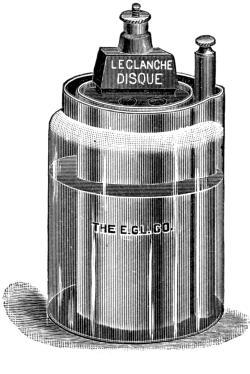
Fig. 52.
To set up a Leclanche cell, proceed as follows: Put six ounces of sal ammoniac into the glass jar; fill the jar one-third full of clear water and stir. Put in the porous cup and fill the jar with water up to its neck, pouring a few teaspoonfuls of water into the hole in[Pg 86] porous cup. When the cell is in working condition, the level of the solution will be found to have receded, owing to absorption by the porous cup. To prevent the creeping of sal ammoniac up the neck of jar and on to the terminals of the cell, a layer of paraffin is applied to neck of jar and porous cup. Should this need renewing, vaseline can be used, or any heavy grease, care being taken that it does not get on electrodes or where the wires are to be fastened. When the cell refuses to work, throw out old solution, wash porous cup, jar and zinc in warm water, and replace with new solution. There is a limit, when a new porous cup must be used, but this can be done when cell does not work after being treated as above. The electromotive force of the Leclanche cell is about 1.45, and current on short circuit of nearly one ampere, depending of course on thickness and porosity of porous cup, size of zinc, and a few other points.
Fig. 53 is one of the Leclanche group, in which a compound carbon element displaces the earthenware porous cup. This[Pg 87] carbon is composed of two parts, a hollow-fluted lower piece and a threaded top, which carries the binding post. In the process of manufacture, the top piece is heated red-hot and plunged into hot paraffin wax, thus ensuring a complete diffusion of the paraffin throughout the carbon. In this way the creeping of salt or solution, and consequent corrosion of electrodes and failure of cell, are avoided. The lower portion is much more porous than the upper and is filled with a combination of pea-carbon and peroxide of manganese held in by a[Pg 88] plug at the bottom. This plug can be removed and new depolarizer added. Directions given by the manufacturers for renewing this element are to hold the lower end of the carbon over a burner flame until the plug is softened and can be removed, or to immerse the extreme lower end of the carbon in boiling water. After refilling, a cork plug can be used.
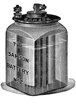
Fig. 53.
The E. M. F. of the No. 2 size is from 1.40 to 1.47 volts, and current, on short circuit, of 12 to 16 amperes. The No. 2 Special has same E. M. F., but current of only 5 amperes, being intended where strong current is not required but quick recuperation. It will be seen that this cell is far more suited to electric gas-lighting work than the simple Leclanche, owing to its great current delivery.
Of so-called dry cells there are numbers on the market at so low a price that it does not pay to make one’s own. But for those who wish to do so, the following formula, furnished by Mr. Wm. Roche, of New Standard battery fame, will be found excellent:
One pint CLEAR WATER.
Five ounces sal ammoniac.
Six ounces zinc chloride.
Dissolve the sal ammoniac in the water thoroughly. Let stand twenty-four hours. Then add the zinc chloride, and when cool, will be ready for use.
When you have your zinc cup ready, pour a little wax in the bottom, to insulate; place a piece of blotting-paper inside cup and laying tight against the zinc, about three turns. The negative element is prepared as follows: One pound pure carbon, powdered; one pound black oxide manganese; mix thoroughly. Then add sufficient of above solution to hold it together without being plastic, as that would be too wet to tamp.
Moisten your paper in the zinc cup thoroughly. Place your stick or plate of carbon in centre of zinc cup, hold it there central while you pack in the carbon manganese element all around it; be sure that carbon manganese, or negative element, does not touch zinc cup. If it does, your cell will run down quickly. It is a good precaution to have your paper half an inch higher than cup[Pg 90] when in the cup, and soaked with the solution. Give it a couple of quick taps on the bench; that will curl the paper in at the bottom and insure against any internal short circuit. When your cell is filled up, clean all the carbon element away from the zinc. Seal, and your battery is ready when you’ve got the connections on.
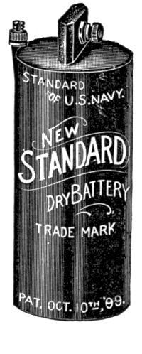
Fig. 54.
The principal sizes of this cell (Fig. 54) are as follows:
No. 2—5-7/8 × 2-7/16.
No. 3—3-3/4 × 1-7/8.
No. 5—6 × 2-9/16.
No. 6—6 × 3.
No. 7—7 × 3.
The electromotive force is 1.5 volts, current of the No. 7 size on short circuit, 24 amperes. Nos. 2, 5, 6, or 7 are most suitable for electric gas lighting, either by simple primary coil or jump spark coil.
This cell (Fig. 55), gives a large, steady current and is of low internal resistance, but its electromotive force is not high, being less than .7 volt on closed circuit. Its output of current varies with the size, type S being .025 ohm internal resistance and capacity of 300 ampere-hours. The Edison Lalande cell can be applied to electric gas lighting in cases where a large demand is made upon the battery, for example in church or theatre lighting.
Its elements consist of positive plates of amalgamated zinc suspended on each side of negative plates of black oxide of copper. The[Pg 92] electrolyte is an aqueous solution of caustic soda. A layer of heavy paraffin oil is poured on top of the solution to prevent the solution from evaporating and also to keep the soda crystals from creeping up and over the rim of the jar.
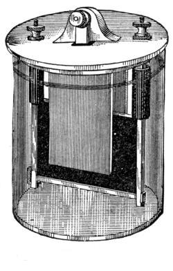
Fig. 55.
To set up an Edison Lalande cell, fill the jar up to the brown mark with clear water; pour in the soda from the tin box, and stir. When thoroughly dissolved, pour on top of the solution one half-inch layer of the oil which is sent with the battery. Then the[Pg 93] elements attached to the cover can be inserted, and the cell is ready for use.
Use care not to splash the solution, as it will burn the clothing and skin. If any does get on, a little animal grease or vegetable oil will quickly saponify it.
In the action of this cell the oxide of copper is reduced to metallic copper and the zincs consumed, it being intended that each element will require renewal at the same time. Upon picking into the oxide plate with a sharp-pointed instrument, if the plate is red throughout, it is exhausted; but, should it show black in its interior, it is still capable of a little more use, but is preferable to use a new plate whenever there is but little oxide left.
Never remove the oxide plates from the battery, and do not allow the solution to be less than one inch above oxide plates.
Although not often necessary in gas-lighting work, there is at times a demand for a heavy current, such as in lighting a big building, where a large coil must be operated. At such times a bichromate of potash cell becomes of[Pg 94] service. One of the types is shown in Fig. 56. J is a jar containing electropoion fluid described below. C is a carbon plate immersed in this fluid. P is a porous cup holding the zinc, Z, and being filled with a solution of 18 parts common salt, 72 parts water, and one ounce mercury.
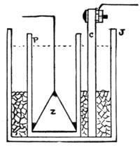
Fig. 56.
The electropoion fluid for the outer jar is made by one pound bichromate of potash or soda to one gallon of water, mixing in a stone vessel. When dissolved, add three pounds commercial sulphuric acid carefully, a little at a time, and stir the mixture constantly as it gets hot. Always add the acid to the mixture; never attempt to pour the mixture into the acid, or trouble will result. The sodium salt is preferable to the potassium, owing to its[Pg 95] greater solubility and its not forming chrome alum—a hard precipitate which sticks to jars, elements, etc., to their detriment.
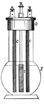
Fig. 57.
Fig. 57, a form of battery known as the Grenet battery, is used where there is no porous cup. The zinc element, Z, is mounted on a rod R passing through the cap G of a glass jar, J, and can be raised or lowered into the electropoion fluid which the jar contains. This is a good scheme where the battery is liable to stand idle for a long period.
Terminals.—Take care that the solutions do not splash over terminals; keep all terminals and binding post screws clean and bright. See that all wires are tightly clamped in terminals, also that their ends are clean. A loose contact is productive of infinite trouble. Examine connections that elements are in proper relation to each other. If in multiple, to produce large current—zincs together and carbons together. If in series, for high electromotive force—zinc to carbon, throughout battery.
Zincs.—See that the zincs are clean; if crystals form, either reduce strength of solution with water, or scrape zincs clean, and watch if repeated. Examine screw which holds wire; it often corrodes, and makes poor contact in the thread.
A clever device for preserving a rod zinc from the accumulation of crystals is made by the manufacturers of the Samson cell. It consists of a thin paper tube which is slipped over the zinc. When the crystals accumulate so as to impair the cell, the tube is slipped off and a new one put on. This device increases[Pg 97] the internal resistance of the cell but very slightly.
Porous cups and carbons.—Wash in warm water. Carbons can be well soaked in warm water and dried in sun, in a place where they will not accumulate dust. Porous cups should be well soaked in warm water, and left to drain in a place exposed to dustless air. Examine binding post holes and screws.
Solutions.—Do not make too strong. Use not more than six ounces, or more than four ounces avoirdupois, of chemically pure sal ammoniac to one cell Leclanche. Warm water can be used for making solutions, if desired. Some persons drop a teaspoonful of acetic acid in the cell; it is not recommended. If in a place where sal ammoniac cannot be procured, use temporarily common table-salt in same proportion; thoroughly well clean battery first.
Batteries should be kept in a cool dry place. Dry cells should stand upright, also in a cool place, and an examination made once in a while of the connections.
New Standard Dry Battery
All sizes for all systems of Bells, Telephones, Burglar Alarms and Gas Lighting. Prices according to size and quantity.
New Standard “Autogas” Dry Battery
For very heavy work. Gas Mobiles, Lights, etc. No. 2 set, weight 27 lbs., neat oak case, $6.00 per set.
New Standard Jump Spark Rhumkorff Coils, $12.00 each.
New Standard Flashlight.
For use around Gasolene Engines, Automobiles, Launches, Clothes Closets, etc. $2.00 each.
This light will positively give equal to fifteen hours actual service. A $5.00 article for $2.00.
Complete catalogue for the asking.
William Roche,
Inventor and M’f’r,
42 Vesey St., N. Y. City
Dealer in Battery Materials,
Chemicals, Etc.
Have a Look Into our Store when in need of anything in the Electrical line of whatever nature.
We deal in everything and carry a good stock.
CATALOGUE ON Electric Light Goods, Bells, and Electric House Goods, Switchboards, &c. Telephones and Supplies.
J. JONES & SON,
64 Cortlandt St., New York City.
JUMP SPARK COILS
X-Ray Coils.
Primary Coils.
Medical Coils.
Telephone Coils.
C. F. SPLITDORF, 17-27 Vandewater St., N. Y.
AMERICAN BOOKS.
Allen, C. F. Railroad Curves and Earthwork. A pocketbook for Surveyors and Engineers. Limp leather, $2.00.
Cordeiro, Dr. F. J. B. The Barometrical Determination of Heights, Levelling and Hypssometry. Limp leather, $1.00.
Goldingham, A. H. The Design and Construction of Oil Engines, with full Instructions for their Erecting, Testing, Running and Repairing. 12mo, cloth, $2.00.
Kinealy, J. H. An Elementary Text-Book on Steam Engines and Boilers. Third edition, cloth $2.00.
Kinealy, J. H. Steam Heating Charts for the use of Architects and Builders in Estimating the Necessary Heat Required for Buildings. $1.00.
Redwood, I. I. Lubricants, Oils and Greases. Cloth, $1.50.
We Mail All Books Postpaid on Receipt of Price.
Address:
SPON & CHAMBERLAIN,
12 Cortlandt Street, New York.
SMALL ACCUMULATORS
How Made and Used
A Practical Handbook for Students and Young
Electricians
EDITED BY PERCIVAL MARSHALL, A.I.M.E.
Contents of Chapters
I.—The Theory of the Accumulator.
II.—How to make a 4-Volt Pocket Accumulator.
III.—How to make a 32-Ampere-Hour Accumulator.
IV.—Types of Small Accumulators.
V.—How to Charge and Use Accumulators.
VI.—Applications of Small Accumulators, Electrical Novelties,
etc. Useful Receipts. Glossary of Technical Terms.
80 pages, 40 illustrations, 12mo, cloth, 50c.
THE MAGNETO-TELEPHONE
ITS CONSTRUCTION,
Fitting Up and Adaptability to Every-Day Use
BY NORMAN HUGHES
CONTENTS OF CHAPTERS
Some electrical considerations: I.—Introductory. II.—Construction. III.—Lines, Indoor Lines. IV.—Signalling Apparatus. V.—Batteries. Open Circuit Batteries. Closed Circuit Batteries. VI.—Practical Operations. Circuit with Magneto Bells and Lightning Arresters. How to Test the Line. Push-Button Magneto Circuit. Two Stations with Battery Bells. VII.—Battery Telephone. Battery Telephone Circuit. Three Instruments on one Line. VIII.—General remarks. Index.
80 pages, 23 illustrations, 12mo, cloth, $1.00. In paper, 50c.
EVERYBODY’S BOOK ON ELECTRICITY
PRACTICAL ELECTRICS
A UNIVERSAL HANDY-BOOK
ON
EVERYDAY ELECTRICAL MATTERS
FIFTH EDITION
CONTENTS:
Alarms.—Doors and Windows; Cisterns; Low Water in Boilers; Time Signals; Clocks. Batteries.—Making; Cells; Bichromate; Bunsen; Callan’s; Copper-oxide; Cruikshank’s; Daniel’s; Granule carbon; Groves; Insulite; Leclanché; Lime Chromate; Silver Chloride; Smee; Thermo-electric. Bells.—Annunciator System; Double System; and Telephone; Making; Magnet for; Bobbins or Coils; Trembling; Single Stroke; Continuous Ringing. Connections. Carbons. Coils.—Induction; Primary; Secondary; Contact-breakers; Resistance. Intensity Coils.—Reel; Primary; Secondary; Core; Contact-breaker; Condenser; Pedestal; Commutator; Connections. Dynamo-electric Machines.—Field-Magnets; Pole-pieces; Field-magnet Coils; Armature Cores and Coils; Commutator Collectors and Brushes; Relation of size to efficiency; Methods of exciting Field-Magnets; Magneto-Dynamos; Separately excited Dynamos; Shunt Dynamos; Field-Magnets; Armatures; Collectors; Brush Dynamo; Alternate Currents. Fire Risks.—Wires; Lamps; Danger to persons. Measuring.—Non-Registering Instruments; Registering Instruments. Microphones. Motors. Phonographs. Photophones. Storage. Telephones.—Forms; Circuits and Calls; Transmitter and Switch; Switch for Simplex; etc., etc.
135 PAGES. 126 ILLUSTRATIONS. 8VO.
Cloth, 75 cents
SAMPLE COPIES MAILED TO ANY ADDRESS ON RECEIPT OF 8 CENTS.
THE MODEL ENGINEER AMATEUR ELECTRICIAN
A Journal of Mechanics and Electricity for Amateurs and Students
Edited by PERCIVAL MARSHALL
ITS GOOD POINTS.
Better than any paper of its kind ever published.
The articles are original and practical.
The articles are so clearly and simply written and everything made so plain that it will be found easy to follow the directions and duplicate the articles described.
Special articles on Model engines and boilers for yachts, torpedo-boats and war-ships.
Designing and building of model yachts and boats.
Making small tools for model work.
The building of small gas engines.
Building screw-cutting and turning lathes.
Building all kinds of model stationary and locomotive steam engines and boilers.
Model engineers and their work.
Building of all kinds of electrical machines, apparatus, coils, batteries, telephones, microphones, phonographs, novelties.
The articles are fully illustrated, principally with detail drawings to scale.
New Books, Notes and Queries, Workshop Notes and Hints, Tools and Supplies, etc.
ANNUAL SUBSCRIPTION, $1.50 POSTPAID
Send in your subscription and get your friends to subscribe. Unused postage stamps will be accepted (not revenue.) Address all communications to
SPON & CHAMBERLAIN,
12 Cortlandt Street, NEW YORK.
Induction Coils
—AND—
COIL MAKING.
Construction, Operation and Application.
By H. S. NORRIE.
Second edition, thoroughly revised and greatly enlarged, and including 25 new illustrations. A good deal of the new matter is devoted to Medical Coils, Bath Coils, Gas Engine and Spark Coils, Contact Breakers, Batteries, X-Ray Work, Electric Gas Lighting, and a chapter on Wireless Telegraphy.
Contents of Chapters.
1. Coil construction, full directions, sizes of wires, &c., &c. 2. Construction of different forms of contact breakers. 3. Insulating materials, cements, &c. 4. Construction of various kinds of condensers. 5. Experiments. 6. Spectrum analysis. 7. Currents in vacuo. 8. Rotating effects. 9. The application of coils to gas lighting. 10. Batteries for coils. 11. Secondary Batteries. 12. Tesla and Hertz effects. 13. X-Rays and radiography. 14. Wireless telegraphy. Contents. Index.
290 pages, 79 Illus. 5 × 6-1/2 in.
CLOTH, $1.00
Manual of Instruction in
Hard Soldering
WITH AN APPENDIX ON THE
Repair of Bicycle Frames
Notes on Alloys and a Chapter on Soft Soldering
BY HARVEY ROWELL
The flame, lamp, charcoal, mats, blow-pipes, wash-bottle, binding wire, chemicals, borax, spelter, silver solder, gold solder, oxidation of metals, fluxes, anti-oxidisers, oxidation of cases, the cone, oxidising flame, reducing flame, heat transmission, conduction, capacity of metals, radiation, application, the work table, the joint, applying solder, applying heat, the use of the blow-pipe, joints, making a ferrule, to repair a spoon, to repair a watch case, hard soldering with a forge or hearth, hard soldering with tongs, preserving thin edges, silversmith’s pickle, restoring color to gold, chromic acid, to mend steel springs, sweating metals together, retaining work in position, making joints, applying heat, preventing the loss of heat, effect of sulphur lead and zinc, to preserve precious stones, annealing and hardening, burnt iron, to hard solder after soft solder. Tables of—specific gravity, tenacity, fusibility, alloys.
66 pages, illustrated, cloth, 75 cents.
For Soldering Receipts, Cements and Lutes, Pastes, Glues and such like, see Workshop Receipts.
NEW
EDITION “DE LUXE”
ON HEAVY PLATE PAPER
A SYSTEM OF EASY LETTERING
BY J. H. CROMWELL.
ITS GOOD POINTS.
Very easy to learn.
A rapid method to become a good letterer with a little practice.
Very easy to lay out a line of words in Strict Proportion, whether it be on a fence 500 yards long or on a drawing only a few inches across.
Good for draughtsmen who prefer neat lettering, yet something out of the ordinary.
It contains 26 pages of alphabets whose modifications are almost limitless.
One of the cheapest in the market.
This little book will be appreciated by draughtsmen who wish to use plain letters (and yet somewhat different from the ordinary run of letters) for the titles on drawings. The book will also be valuable and useful to any one who has had no practice in lettering, as the easy method given for forming the letters will enable a person to form the letters correctly, and with a little practice to do so quickly.—American Machinist.
Oblong, 8vo, cloth, 50 cents
Workshop Receipts.
THE MOST COMPLETE
Technical Cyclopedia in 5 Vols.
First Series. Principal Contents.—Bronzes, Cements, Dyeing, Electro-metallurgy, Enamels, Etchings, Fireworks, Fluxes, Fulminates, Gilding, Gums, Japanning, Lacquers, Marble Working, Nitro-Glycerine, Photography, Pottery, Varnishes, 420 pages, 103 illus., cloth, $2.00.
Second Series. Principal Contents.—Acidimetry, Albumen Alcohol, Alkaloids, Bitters, Bleaching, Boiler Incrustations, Cleansing, Confectionery, Copying, Disinfectants, Essences, Extracts, Fire-proofing, Glycerine, Gut, Iodine, Ivory Substitutes, Leather Matches Pigments, Paint, Paper, Parchment. 485 pages, 16 illus., cloth, $2.00.
Third Series. Principal Contents.—Alloys, Aluminium, Antimony, Copper, Electrics, Enamels, Glass, Gold, Iron, Steel, Liquors Lead, Lubricants, Magnesium, Manganese, Mercury, Mica, Nickel, Platinum, Silver, Slag, Tin, Uranium, Zinc. 480 pages, 183 illus., cloth, $2.00.
Fourth Series. Principal Contents.—Waterproofing, Packing, Stowing, Embalming, Preserving, Leather Polishes, Cooling Air and Water, Pumps and Siphons, Dessicating, Distilling, Emulsifying, Evaporating, Filtering, Percolating, Macerating, Electrotyping, Stereotyping, Book-binding, Straw-plaiting, Musical Instruments, Clock and Watch Mending, Photography 443 pages, 243 illus., cloth. $2.00.
Fifth Series. Principal Contents.—Diamond Cutting, Laboratory Apparatus, Filtering, Magic Lanterns Metal Work, Percolation, Illuminating Agents, Tobacco Pipes, Taps, Tying and Splicing Tackle, Repairing Books, Netting, Walking Sticks, Boat-Building. 440 pages, 373 illus., cloth, $2.00.
EACH SERIES has its own Contents
and Index and is complete in itself.
The Best and Cheapest in the Market
ALGEBRA SELF-TAUGHT
FOR THE USE OF
Mechanics, Young Engineers and Home Students
BY W. PAGET HIGGS, M.A., D.Sc.
FOURTH EDITION
CONTENTS
Symbols and the signs of operation. The equation and the unknown quantity. Positive and negative quantities. Multiplication, involution, exponents, negative exponents, roots, and the use of exponents as logarithms. Logarithms. Tables of logarithms and proportional parts. Transportation of systems of logarithms. Common uses of common logarithms. Compound multiplication and the binomial theorem. Division, fractions and ratio. Rules for division. Rules for fractions. Continued proportion, the series and the summation of the series. Examples. Geometrical means. Limit of series. Equations. Appendix. Index. 104 pages, 12mo, cloth, 60c.
See also Algebraic Signs, Spons’ Dictionary of Engineering, No. 2. 40 cts.
See also Calculus, Supplement to Spons’ Dictionary, No. 5. 75 cts.
CROSS SECTION PAPER.
THE HANDY SKETCHING PAD.
Printed on one side, in blue ink, all the lines being of equal thickness, with useful tables. Size 8 × 10 inches. Price, 25c. each. Per dozen pads, $2.50.
THE HANDY SKETCHING BOOK.
Made from this paper but printed on both sides. Size of book 5 × 8 inches, stiff board covers. Price, 25c. each; per dozen books, $2.50.
SCALE EIGHT TO ONE INCH.
A large sheet with heavy inch lines and half inch lines, printed in blue ink. Size of sheet, 17 × 22 inches. Per quire (24 sheets), 75c.
SCALE TEN TO ONE INCH.
Size 17 × 22 inches, printed in blue ink, with heavy inch lines and half inch lines. Per quire (24 sheets), 75c.
THE ELECTRICIAN’S SKETCHING PAD.
Size 8 × 10. Scale 10 to 1 in. Price 25c. each. Per dozen, $2.50.
THE ELECTRICIAN’S SKETCHING BOOK.
Made from this paper. Scale 10 to 1 inch. Size of book 5 × 8 inches, with stiff board covers. Price, 25c. each; per dozen, $2.50.
Any quantity mailed to any part of the world on receipt of price.
Or Books and Pads Assorted, per dozen, $2.50.
This paper is not ruled. Try it and you will find it
GOOD, ACCURATE AND CHEAP.
SPON & CHAMBERLAIN, 12 Cortlandt St.,
NEW YORK.
PRACTICAL HANDBOOK ON
Gas Engines
With Instructions for Care and Working of the Same.
BY G. LIECKFELD, C.E.
Translated with permission of the Author by
GEORGE RICHMOND, M.E.
WITH A CHAPTER ON OIL ENGINES
CONTENTS
Choosing and installing a gas engine. The construction of good gas engines. Examination as to workmanship, running, economy. Reliability and durability of gas engines. Proper erection of a gas engine. Foundation. Arrangement for gas pipes. Rubber bag. Locking devices. Exhaust pipes. Air pipes. Setting up gas engines. Brakes and their use in ascertaining the power of gas engines. Arrangement of a brake test. Distribution of heat in a gas engine. Attendance on gas engines. General remarks. Gas engine oil. Cylinder lubricators. Rules as to starting and stopping a gas engine. The cleaning of a gas engine. General observations and specific examination for defects. The engine refuses to work. Non-starting of the engine. Too much pressure on the gas. Water in the exhaust pot. Difficulty in starting the engine. Irregular running. Loss of power. Weak gas mixtures. Late ignition. Cracks in air inlet. Back firing. Knocking and pounding inside of engine. Dangers and precautionary measure in handling gas engines. Precautions when opening gas valves, removing piston from cylinder, examining with light openings of gas engines. Dangers in starting, cleaning, putting on belts. Oil Engines. Gas engines with producer gas. Gasoline and oil engines. Concluding remarks.
120 pages, illustrated, l2mo, cloth, $1.00.
THE
FIREMAN’S GUIDE
A Handbook on the Care of Boilers
BY KARL P. DAHLSTROM, M.E.
CONTENTS OF CHAPTERS
I. Firing and Economy of Fuel.—Precautions before and after starting the fire, care of the fire, proper firing, draft, smoke, progress of firing, fuel on the grate, cleaning out, cleaning grate bars and ash pan, dampers, firing into two or more furnaces, dry fuel, loss of heat.
II. Feed and Water Line.—Feeding, the water line, false water line, defective feeding apparatus, formation of scale, gauge cocks, glass gauge, the float, safety plug, alarm whistle.
III. Low Water and Foaming or Priming.—Precautions when water is low, foaming, priming.
IV. Steam Pressure.—Steam gauge, safety valves.
V. Cleaning and Blowing Out.—Cleaning the boiler, to examine the state of the boiler, blowing out, refilling the boiler.
VI. General Directions.—How to prevent accidents, repairs, the care of the boiler when not in use, testing boilers, trimming and cleaning outside. Summary of rules. Index.
8vo, cloth, 50 cents.
HOW TO RUN
Engines and Boilers
Practical Instruction for Young Engineers and
Steam Users.
BY EGBERT POMEROY WATSON
REVISED AND ENLARGED
Synopsis of Contents
Cleaning the boiler, removing scale, scale preventers, oil in boilers, braces and stays, mud drums and feed pipes, boiler fittings, grate bars and tubes, bridge walls, the slide valve, throttling engine, the piston, testing the slide valve with relation to the ports, defects of the slide valve, lap and lead, the pressure on a slide valve, stem connections to the valve, valves off their seats, valve stem guides, governors, running with the sun, eccentrics and connections, the crank pin, brass boxes, bearings on pins, adjustment of bearings, the valve and gearing, setting eccentrics, the actual operation, return crank motion, pounding, the connections, lining up engines, making joints, condensing engines, Torricelli’s vacuum, proof of atmospheric pressure, pumps, no power in a vacuum, supporting a water column by the atmosphere, starting a new plant, the highest qualities demanded.
Water tube boilers, fire tube boilers, why water tube boilers steam rapidly, torpedo boat boilers, management of water tube boilers, economy and maintenance of water tube boilers.
150 pages, illustrated, 16mo, cloth, $1.00.
THE CORLISS ENGINE.
By John T. Henthorn.
—AND—
MANAGEMENT OF THE CORLISS ENGINE.
By Charles D. Thurber.
Uniform in One Volume. Cloth Cover; Price, $1.00.
Table of Contents.
Chapter I.—Introductory and Historical; Steam Jacketing. Chapter II.—Indicator Cards. Chapter III.—Indicator Cards continued; the Governor. Chapter IV.—Valve Gear and Eccentric; Valve Setting. Chapter V.—Valve Setting continued, with diagrams of same; Table for laps of Steam Valve. Chapter VI.—Valve Setting continued. Chapter VII.—Lubrication with diagrams for same. Chapter VIII.—Discussion of the Air Pump and its Management. Chapter IX.—Care of Main Driving Gears; best Lubricator for same. Chapter X.—Heating of Mills by Exhaust Steam. Chapter XI.—Engine Foundations; diagrams and templets for same. Chapter XII.—Foundations continued; Materials for same, etc.
Third Edition, with an Appendix.
THE SLIDE VALVE
SIMPLY EXPLAINED
By W. J. TENNANT, Asso. M.I.M.E.
REVISED AND MUCH ENLARGED
By J. H. KINEALY, D.E.
CONTENTS OF CHAPTERS:
I. The Simple Slide.
II. The Eccentric a Crank. Special Model to Give Quantitative Results.
III. Advance of the Eccentric.
IV. Dead Centre. Order of Cranks. Cushioning and Lead.
V. Expansion—Inside and Outside Lap and Lead; Advance Affected Thereby. Compression.
VI. Double-Ported and Piston Valves.
VII. The Effect of Alterations to Valve and Eccentric.
VIII. Note on Link Motions.
IX. Note on Very Early Cut-Off, and on Reversing Gears in General.
88 Pages. 41 Illustrations. 12mo, Cloth, $1.00.
QUICK AND EASY METHODS
OF
Calculating
With the Slide Rule
A Simple Explanation of the Theory and
Use of the Slide Rule, Logarithms, Etc.
With numerous examples worked out.
By R. G. BLAINE, M.E.
A most reliable, practical and valuable work for the engineer.
144 Pages. Illustrated. 12mo, Cloth, $1.00
THEORETICAL AND PRACTICAL
Ammonia Refrigeration
A Work of Reference for Engineers and others Employed in the
Management of Ice and Refrigeration Machinery.
By ILTYD I. REDWOOD
CONTENTS
B. T. U. Mechanical Equivalent of a Unit of Heat. Specific Heat. Latent Heat. Theory of Refrigeration. Freezing, by Compressed Air. Ammonia. Characteristics of Ammonia. The Compressor. Stuffing-Boxes. Lubrication. Suction and Discharge Valves. Separator. Condenser-Worm, Receiver. Refrigerator or Brine Tank. Size of Pipe and Area of Cooling Surface. Charging the Plant with Ammonia. Jacket-Water, for Compressor, for Separator. Quantity of Condensing Water Necessary. Loss due to Heating of Condensed Ammonia. Cause of Variation in Excess Pressure. Use of Condensing Pressure in Determining Loss of Ammonia by Leakage. Cooling Directly by Ammonia. Freezing Point of Brine. Making Brine. Specific Heat of Brine. Regulation of Brine Temperature. Indirect Effect of Condensing Water on Brine Temperature. Directions for Determining Refrigerating Efficiency. Equivalent of a Ton of Ice. Compressor Measurement of Ammonia Circulated. Loss of Well-Jacketed Compressors. Loss in Double-Acting Compressors. Distribution of Mercury Wells. Examination of Working Parts. Indicator Diagrams. Ammonia Figures—Effectual Displacement. Volume of Gas. Ammonia Circulated per Twenty-Four Hours. Refrigerating Efficiency. Brine Figures—Gallons Circulated. Pounds Circulated. Degrees Cooled. Total Degrees Extracted. Loss due to Heating of Ammonia Gas. Loss due to Heating of Liquid Ammonia. Calculation of the Maximum Capacity of a Machine. Preparation of Anhydrous Ammonia. Construction of Apparatus, etc., etc.
150 pages, 15 illustrations, cloth, $1.00.
Spons’ $2.50
MECHANIC’S OWN BOOK,
A PRACTICAL MANUAL.
Principal Contents.
Mechanical Drawing. (13 pages).
Casting and Founding. (31 pages).
Forging and Finishing. (56 pages.)
Soldering. (26 pages).
Sheet-Metal Working. (10 pages).
Carpentry, Woods, Tools, etc. (224 pages).
Cabinet Making. (36 pages).
Carving and Fretwork. (13 pages).
Upholstery. (6 pages).
Painting, Graining and Marbling. (28 pages).
Staining, and Gilding. (16 pages).
Polishing, Varnishing. (26 pages).
Mechanical Movements. (56 pages).
Turning and Lathe work. (30 pages).
Masonry, Stonework, Brickwork, Concrete, etc. (45 pages).
Plastering, Whitewashing, Paperhanging. (13 pages)
Roofing, Glazing. (14 pages).
Bell hanging, Gas fitting. (8 pages).
Lighting, Ventilation, Warming. (21 pages).
Foundations, Roads and Bridges, Banks, Hedges, Ditches and Drains, Water Supply and Sanitation. House Construction, etc. Size of book 6-3/4 in. by 8-3/4.
702 pages, half extra gilt and 1420 illustrations.