
THE MACMILLAN COMPANY
NEW YORK · BOSTON · CHICAGO · DALLAS
ATLANTA · SAN FRANCISCO
MACMILLAN & CO., Limited
LONDON · BOMBAY · CALCUTTA
MELBOURNE
THE MACMILLAN CO. OF CANADA, Ltd.
TORONTO
 Even the tiny trout brook becomes a thing of utility as well as of
joy
Even the tiny trout brook becomes a thing of utility as well as of
joyLIGHT, HEAT AND POWER BY INEXPENSIVE
METHODS FROM THE WATER
WHEEL OR FARM ENGINE
AUTHOR OF "THE FARMER OF TO-MORROW," ETC., ETC.
New York
THE MACMILLAN COMPANY
1915
All rights reserved
Copyright, 1915
By THE CURTIS PUBLISHING COMPANY
The Country Gentleman
Copyright, 1915
By THE MACMILLAN COMPANY
Set up and electrotyped. Published April, 1915.
This book is designed primarily to give the farmer a practical working knowledge of electricity for use as light, heat, and power on the farm. The electric generator, the dynamo, is explained in detail; and there are chapters on electric transmission and house-wiring, by which the farm mechanic is enabled to install his own plant without the aid and expense of an expert.
With modern appliances, within the means of the average farmer, the generation of electricity, with its unique conveniences, becomes automatic, provided some dependable source of power is to be had—such as a water wheel, gasoline (or other form of internal combustion) engine, or the ordinary windmill. The water wheel is the ideal prime mover for the dynamo in isolated plants. Since water-power is running to waste on tens of thousands of our[Pg vi] farms throughout the country, several chapters are devoted to this phase of the subject: these include descriptions and working diagrams of weirs and other simple devices for measuring the flow of streams; there are tables and formulas by which any one, with a knowledge of simple arithmetic, may determine the power to be had from falling water under given conditions; and in addition, there are diagrams showing in general the method of construction of dams, bulkheads, races, flumes, etc., from materials usually to be found on a farm. The tiny unconsidered brook that waters the farm pasture frequently possesses power enough to supply the farmstead with clean, cool, safe light in place of the dangerous, inconvenient oil lamp; a small stream capable of developing from twenty-five to fifty horsepower will supply a farmer (at practically no expense beyond the original cost of installation) not only with light, but with power for even the heavier farm operations, as threshing; and in addition will do the washing, ironing, and cooking, and at the[Pg vii] same time keep the house warm in the coldest weather. Less than one horsepower of energy will light the farmstead; less than five horsepower of energy will provide light and small power, and take the drudgery out of the kitchen.
For those not fortunate enough to possess water-power which can be developed, there are chapters on the use of the farm gasoline engine and windmill, in connection with the modern storage battery, as sources of electric current.
It is desired to make acknowledgment for illustrations and assistance in gathering material for the book, to the editors of The Country Gentleman, Philadelphia, Pa.; The Crocker-Wheeler Company, Ampere, N. J.; The General Electric Company, Schenectady, N. Y.; the Weston Electrical Instrument Company, of Newark, N. J.; The Chase Turbine Manufacturing Company, Orange, Mass.; the C. P. Bradway Machine Works, West Stafford, Conn.; The Pelton Water Wheel Company, San Francisco and New[Pg viii] York; the Ward Leonard Manufacturing Company, Bronxville, N. Y.; The Fairbanks, Morse Company, Chicago; and the Fitz Water Wheel Company, Hanover, Pa.
| INTRODUCTION | xvii |
| PART I | |
| WATER-POWER | |
| CHAPTER I | |
| A WORKING PLANT | |
| The "agriculturist"—An old chair factory—A neighbor's home-coming—The idle wheel in commission again—Light, heat and power for nothing—Advantages of electricity | 3 |
| CHAPTER II | |
| A LITTLE PROSPECTING | |
| Small amount of water required for an electric plant—Exploring, on a dull day—A rough and ready weir—What a little water will do—The water wheel and the dynamo—Electricity consumed the instant it is produced—The price of the average small plant, not counting labor | 22 |
| CHAPTER III | |
| HOW TO MEASURE WATER-POWER | |
| What is a horsepower?—How the Carthaginians manufactured horsepower—All that goes up must come down—How the sun lifts water up for us to use—Water the ideal power for generating electricity—The weir—Table for estimating flow of streams with a weir—Another method of measuring—Figuring water horsepower—The size of the wheel—What head is required—Quantity of water necessary | 32 |
| CHAPTER IV | |
| THE WATER WHEEL AND HOW TO INSTALL IT | |
| Different types of water wheels—The impulse and the reaction wheels—The impulse wheel adapted to high heads and small amount of water—Pipe lines—Table of resistance in pipes—Advantages and disadvantages of the impulse wheel—Other forms of impulse wheels—The reaction turbine, suited to low heads and large quantity of water—Its advantages and limitations—Developing a water-power project: the dam; the race; the flume; the penstock; and the tailrace—Water rights for the farmer | 56 |
| PART II | |
| ELECTRICITY | |
| CHAPTER V | |
| THE DYNAMO; WHAT IT DOES, AND HOW | |
| Electricity compared to the heat and light of the Sun—The simple dynamo—The amount of electric energy a dynamo will generate—The modern dynamo—Measuring power in terms of electricity—The volt—The ampere—The ohm—The watt and the kilowatt—Ohm's Law of the electric circuit, and some examples of its application—Direct current, and alternating current—Three types of direct-current dynamos: series, shunt, and compound | 89 |
| CHAPTER VI | |
| WHAT SIZE PLANT TO INSTALL | |
| The farmer's wife his partner—Little and big plants—Limiting factors—Fluctuations in water supply—The average plant—The actual plant—Amount of current required for various operations—Standard voltage—A specimen allowance for electric light—Heating and cooking by electricity—Electric power: the electric motor | 121 |
| CHAPTER VII | |
| TRANSMISSION LINES | |
| Copper wire—Setting of poles—Loss of power in transmission—Ohm's Law and examples of how it is used in figuring size of wire—Copper-wire tables—Examples of transmission lines—When to use high voltages—Over-compounding a dynamo to overcome transmission loss | 153 |
| CHAPTER VIII | |
| WIRING THE HOUSE | |
| The insurance code—Different kinds of wiring described—Wooden moulding cheap and effective—The distributing panel—Branch circuits—Protecting the circuits—The use of porcelain tubes and other insulating devices—Putting up chandeliers and wall-brackets—"Multiple" connections—How to connect a wall switch—Special wiring required for heat and power circuits—Knob and cleat wiring, its advantages and disadvantages | 172 |
| CHAPTER IX | |
| THE ELECTRIC PLANT AT WORK | |
| Direct-connected generating sets—Belt drive—The switchboard—Governors and voltage regulators—Methods of achieving constant pressure at all loads: Over-compounding the dynamo; A system of resistances (a home-made electric radiator); Regulating voltage by means of the rheostat—Automatic devices—Putting the plant in operation | 192 |
| PART III | |
| GASOLINE ENGINES, WINDMILLS, ETC. THE STORAGE BATTERIES |
|
| CHAPTER X | |
| GASOLINE ENGINE PLANTS | |
| The standard voltage set—Two-cycle and four-cycle gasoline engines—Horsepower, and fuel consumption—Efficiency of small engines and generators—Cost of operating a one-kilowatt plant | 217 |
| CHAPTER XI | |
| THE STORAGE BATTERY | |
| What a storage battery does—The lead battery and the Edison battery—Economy of tungsten lamps for storage batteries—The low-voltage battery for electric light—How to figure the capacity of a battery—Table of light requirements for a farm house—Watt-hours and lamp-hours—The cost of storage battery current—How to charge a storage battery—Care of storage batteries | 229 |
| CHAPTER XII | |
| BATTERY CHARGING DEVICES | |
| The automatic plant most desirable—How an automobile lighting and starting system works—How the same results can be achieved in house lighting, by means of automatic devices—Plants without automatic regulation—Care necessary—The use of heating devices on storage battery current—Portable batteries—An electricity "route"—Automobile power for lighting a few lamps | 250 |
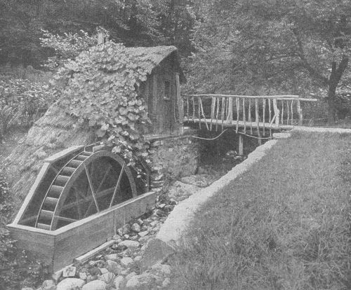
Even the tiny trout brook becomes a thing of utility as well as of joy
Farm labor and materials built this crib and stone dam
Measuring a small stream with a weir
Efficient modern adaptations of the archaic undershot
and overshot water wheels
A direct-current dynamo or motor, showing details of
construction
Details of voltmeter or ammeter
Instantaneous photograph of high-pressure water jet being
quenched by buckets of a tangential wheel
A tangential wheel, and a dynamo keyed to the same
shaft—the ideal method for generating electricity
A rough-and-ready farm electric plant, supplying two
farms with light, heat and power; and a Ward
Leonard-type circuit breaker for charging storage
batteries
The sight of a dozen or so fat young horses and mares feeding and frolicking on the wild range of the Southwest would probably inspire the average farmer as an awful example of horsepower running to waste. If, by some miracle, he came on such a sight in his own pastures, he would probably consume much time practising the impossible art of "creasing" the wild creatures with a rifle bullet—after the style of Kit Carson and other free rovers of the old prairies when they were in need of a new mount. He would probably spend uncounted hours behind the barn learning to throw a lariat; and one fine day he would sally forth to capture a horsepower or two—and, once captured, he would use strength and strategy breaking the wild beast to harness. A single horsepower—animal—will do the work of lifting 23,000 pounds one foot in one minute, providing the animal is[Pg xviii] young, and sound, and is fed 12 quarts of oats and 10 or 15 pounds of hay a day, and is given a chance to rest 16 hours out of 24—providing also it has a dentist to take care of its teeth occasionally, and a blacksmith chiropodist to keep it in shoes. On the hoof, this horsepower is worth about $200—unless the farmer is looking for something fancy in the way of drafters, when he will have to go as high as $400 for a big fellow. And after 10 or 15 years, the farmer would look around for another horse, because an animal grows old.
This animal horsepower isn't a very efficient horsepower. In fact, it is less than three-fourths of an actual horsepower, as engineers use the term. A real horsepower will do the work of lifting 33,000 pounds one foot in one minute—or 550 pounds one foot in one second. Burn a pint of gasoline, with 14 pounds of air, in a gasoline engine, and the engine will supply one 33,000-pound horsepower for an hour. The gasoline will cost about 2 cents, and the air is supplied free. If it was the air that cost two cents a pound, instead of the[Pg xix] gasoline, the automobile industry would undoubtedly stop where it began some fifteen years ago. It is human nature, however, to grumble over this two cents.
Yet the average farmer who would get excited if sound young chunks and drafters were running wild across his pastures, is not inspired by any similar desire of possession and mastery by the sight of a brook, or a rivulet that waters his meadows. This brook or river is flowing down hill to the sea. Every 4,000 gallons that falls one foot in one minute; every 400 gallons that falls 10 feet in one minute; or every 40 gallons that falls 100 feet in one minute, means the power of one horse going to waste—not the $200 flesh-and-blood kind that can lift only 23,000 pounds a foot a minute—but the 33,000 foot-pound kind. Thousands of farms have small streams in their very dooryard, capable of developing five, ten, twenty, fifty horsepower twenty-four hours a day, for the greater part of the year. Within a quarter of a mile of the great majority of farms (outside of the[Pg xx] dry lands themselves) there are such streams. Only a small fraction of one per cent of them have been put to work, made to pay their passage from the hills to the sea.
The United States government geological survey engineers recently made an estimate of the waterfalls capable of developing 1,000 horsepower and over, that are running to waste, unused, in this country. They estimated that there is available, every second of the day and night, some 30,000,000 horsepower, in dry weather—and twice this during the eight wet months of the year. The waterfall capable of giving up 1,000 horsepower in energy is not the subject of these chapters. It is the small streams—the brooks, the creeks, the rivulets—which feed the 1,000 horsepower torrents, make them possible, that are of interest to the farmer. These small streams thread every township, every county, seeking the easiest way to the main valleys where they come together in great rivers.
What profitable crop on your farm removes[Pg xxi] the least plant food? A bee-farmer enters his honey for the prize in this contest. Another farmer maintains that his ice-crop is the winner. But electricity generated from falling water of a brook meandering across one's acres, comes nearer to the correct answer of how to make something out of nothing. It merely utilizes the wasted energy of water rolling down hill—the weight of water, the pulling power of gravity. Water is still water, after it has run through a turbine wheel to turn an electric generator. It is still wet; it is there for watering the stock; and a few rods further down stream, where it drops five or ten feet again, it can be made to do the same work over again—and over and over again as long as it continues to fall, on its journey to the sea. The city of Los Angeles has a municipal water plant, generating 200,000 horsepower of electricity, in which the water is used three times in its fall of 6,000 feet; and in the end, where it runs out of the race in the valley, it is sold for irrigation.
One water-horsepower will furnish light[Pg xxii] for the average farm; five water-horsepower will furnish light and power, and do the ironing and baking. The cost of installing a plant of five water-horsepower should not exceed the cost of one sound young horse, the $200 kind—under conditions which are to be found on thousands of farms and farm communities in the East, the Central West, and the Pacific States. This electrical horsepower will work 24 hours a day, winter and summer, and the farmer would not have to grow oats and hay for it on land that might better be used in growing food for human beings. It would not become "aged" at the end of ten or fifteen years, and the expense of maintenance would be practically nothing after the first cost of installation. It would require only water as food—waste water. Two hundred and fifty cubic feet of water a minute, falling ten feet, will supply the average farm with all the conveniences of electricity. This is a very modest creek—the kind of brook or creek that is ignored by the man who would think time well spent in putting in a week[Pg xxiii] capturing a wild horse, if a miracle should send such a beast within reach. And the task of harnessing and breaking this water-horsepower is much more simple and less dangerous than the task of breaking a colt to harness.
WATER-POWER
A WORKING PLANT
The "agriculturist"—An old chair factory—A neighbor's home-coming—The idle wheel in commission again—Light, heat and power for nothing—Advantages of electricity.
Let us take an actual instance of one man who did go ahead and find out by experience just how intricate and just how simple a thing electricity from farm water-power is. This man's name was Perkins, or, we will call him that, in relating this story.
Perkins was what some people call, not a farmer, but an "agriculturist,"—that is, he was a back-to-the-land man. He had been born and raised on a farm. He knew that you must harness a horse on the left side, milk a cow on the right, that wagon nuts tighten the way the wheel rims, and that a fresh egg will not float.
He had a farm that would grow enough clover to fill the average dairy if he fed it lime; he had a boy coming to school age; and both he and his wife wanted to get back to the country. They had their little savings, and they wanted, first of all, to take a vacation, getting acquainted with their farm. They hadn't taken a vacation in fifteen years.
He moved in, late in the summer, and started out to get acquainted with his neighbors, as well as his land. This was in the New England hills. Water courses cut through everywhere. In regard to its bountiful water supply, the neighborhood had much in common with all the states east of the Mississippi, along the Atlantic seaboard, in the lake region of the central west, and in the Pacific States. With this difference; the water courses in his neighborhood had once been of economic importance.
A mountain river flowed down his valley. Up and down the valley one met ramshackle mills, fallen into decay. Many years ago before railroads came, before it was easy to[Pg 5] haul coal from place to place to make steam, these little mills were centers of thriving industries, which depended on the power of falling water to make turned articles, spin cotton, and so forth. Then the railroads came, and it was easy to haul coal to make steam. And the same railroads that hauled the coal to make steam, were there to haul away the articles manufactured by steam power. So in time the little manufacturing plants on the river back in the hills quit business and moved to railroad stations. Then New England, from being a manufacturing community made up of many small isolated water plants, came to be a community made up of huge arteries and laterals of smoke stacks that fringed the railroads. Where the railroad happened to follow a river course—as the Connecticut River—the water-power plants remained; but the little plants back in the hills were wiped off the map—because steam power with railroads at the front door proved cheaper than water-power with railroads ten miles away.
One night Perkins came in late from a long drive with his next-door neighbor. He had learned the first rule of courtesy in the country, which is to unhitch his own side of the horse and help back the buggy into the shed. They stumbled around in the barn putting up the horse, and getting down hay and grain for it, by the light of an oil lantern, which was set on the floor in a place convenient to be kicked over. He went inside and took supper by the light of a smoky smelly oil lamp, that filled the room full of dark corners; and when supper was over, the farmwife groped about in the cellar putting things away by the light of a candle.
The next day his neighbor was grinding cider at his ramshackle water mill—one of the operations for which a week must be set aside every fall. Perkins sat on a log and listened to the crunch-crunch of the apples in the chute, and the drip of the frothy yellow liquid that fell into waiting buckets.
"How much power have you got here?" he asked.
"Thirty or forty horsepower, I guess."
"What do you do with it, besides grinding cider to pickle your neighbors' digestion with?"
"Nothing much. I've got a planer and a moulding machine in there, to work up jags of lumber occasionally. That's all. This mill was a chair-factory in my grandfather's day, back in 1830."
"Do you use it thirty days in a year?"
"No; not half that."
"What are you going to do with it this winter?"
"Nothing; I keep the gate open and the wheel turning, so it won't freeze, but nothing else. I am going to take the family to Texas to visit my wife's folks for three months. We've worked hard enough to take a vacation."
"Will you rent me the mill while you are gone?"
"Go ahead; you can have it for nothing, if you will watch the ice."
"All right; let me know when you come[Pg 8] back and I'll drive to town and bring you home."
Three months went by, and one day in February the city man, in response to a letter, hitched up and drove to town to bring his neighbor back home. It was four o'clock in the afternoon when they started out, and it was six—dark—when they turned the bend in the road to the farm house. They helped the wife and children out, with their baggage, and as Perkins opened the door of the house, he reached up on the wall and turned something that clicked sharply.
Instantly light sprang from everywhere. In the barn-yard a street lamp with an 18-inch reflector illuminated all under it for a space of 100 feet with bright white rays of light. Another street lamp hung over the watering trough. The barn doors and windows burst forth in light. There was not a dark corner to be found anywhere. In the house it was the same. Perkins led the amazed procession from room to room of the house they had[Pg 9] shut up for the winter. On the wall in the hall outside of every room was a button which he pushed, and the room became as light as day before they entered. The cellar door, in opening, automatically lighted a lamp illuminating that cavern as it had never been lighted before since the day a house was built over it.
Needless to say, the farmer and his family were reduced to a state of speechlessness.
"How the deuce did you do it?" finally articulated the farmer.
"I put your idle water wheel to work," said Perkins; and then, satisfied with this exhibition, he put them back in the sleigh and drove to his home, where his wife had supper waiting.
While the men were putting up the team in the electric lighted barn, the farmwife went into the kitchen. Her hostess was cooking supper on an electric stove. It looked like a city gas range and it cooked all their meals, and did the baking besides. A hot-water tank[Pg 10] stood against the wall, not connected to anything hot, apparently. But it was scalding hot, by virtue of a little electric water heater the size of a quart tin can, connected at the bottom. Twenty-four hours a day the water wheel pumped electricity into that "can," so that hot water was to be had at any hour simply by turning a faucet. In the laundry there was an electric pump that kept the tank in the attic filled automatically. When the level of water in this tank fell to a certain point, a float operated a switch that started the pump; and when the water level reached a certain height, the same float stopped the pump. A small motor, the size of a medium Hubbard squash operated a washing machine and wringer on wash days. This same motor was a man-of-all-work for this house, for, when called on, it turned the separator, ground and polished knives and silverware, spun the sewing machine, and worked the vacuum cleaner.
Over the dining room table hung the same hanging shade of old days, but the oil lamp[Pg 11] itself was gone. In its place was a 100-watt tungsten lamp whose rays made the white table cloth fairly glisten. The wires carrying electricity to this lamp were threaded through the chains reaching to the ceiling, and one had to look twice to see where the current came from. In the sitting room, a cluster of electric bulbs glowed from a fancy wicker work basket that hung from the ceiling. The housewife had made use of what she had throughout the house. Old-fashioned candle-shades sat like cocked hats astride electric bulbs. There is little heat to an electric bulb for the reason that the white-hot wire that gives the light is made to burn in high vacuum, which transmits heat very slowly. The housewife had taken advantage of this fact and from every corner gleamed lights dressed in fancy designs of tissue paper and silk.
"Now we will talk business," said Perkins when supper was over and they had lighted their pipes.
The returned native looked dubious. His New England training had warned him long[Pg 12] ago that one cannot expect to get something for nothing, and he felt sure there was a joker in this affair.
"How much do I owe you?" he asked.
"Nothing," said Perkins. "You furnish the water-power with your idle wheel, and I furnish the electric installation. This is only a small plant I have put in, but it gives us enough electricity to go around, with a margin for emergencies. I have taken the liberty of wiring your house and your horse-barn and cow-barn and your barn-yard. Altogether, I suppose you have 30 lights about the place, and during these long winter days you will keep most of them going from 3 to 5 hours a night and 2 or 3 hours in the early morning. If you were in town, those lights would cost you about 12 cents an hour, at the commercial rate of electricity. Say 60 cents a day—eighteen dollars a month. That isn't a very big electric light bill for some people I know in town—and they consider themselves lucky to have the privilege of buying electricity at that rate. Your wheel is running all winter to[Pg 13] prevent ice from forming and smashing it. It might just as well be spinning the dynamo.
"If you think it worth while," continued Perkins,—"this $18 worth of light you have on tap night and morning, or any hour of the day,—we will say the account is settled. That is, of course, if you will give me the use of half the electricity that your idle wheel is grinding out with my second-hand dynamo. We have about eight electrical horsepower on our wires, without overloading the machine. Next spring I am going to stock up this place; and I think about the first thing I do, when my dairy is running, will be to put in a milking machine and let electricity do the milking for me. It will also fill my silo, grind my mowing-machine knives, saw my wood, and keep water running in my barn. You will probably want to do the same.
"But what it does for us men in the barn and barn-yard, isn't to be compared to what it does for the women in the house. When my wife wants a hot oven she presses a button. When she wants to put the 'fire' out, she presses[Pg 14] another. That's all there is to it. No heat, no smoke, no ashes. The same with ironing—and washing. No oil lamps to fill, no wicks to trim, no chimneys to wash, no kerosene to kick over and start a fire."
"You say the current you have put in my house would cost me about $18 a month, in town."
"Yes, about that. Making electricity from coal costs money."
"What does it cost here?"
"Practically nothing. Your river, that has been running to waste ever since your grandfather gave up making chairs, does the work. There is nothing about a dynamo to wear out, except the bearings, and these can be replaced once every five or ten years for a trifle. The machine needs to be oiled and cared for—fill the oil cups about once in three days. Your water wheel needs the same attention. That's all there is to it. You can figure the cost of your current yourself—just about the cost of the lubricating oil you use—and the cost of the time you give it—about the same time[Pg 15] you give to any piece of good machinery, from a sulky plow to a cream separator."
This is a true story. This electric plant, where Perkins furnishes the electric end, and his neighbor the water-power, has been running now for two years, grinding out electricity for the two places twenty-four hours a day. Perkins was not an electrical engineer. He was just a plain intelligent American citizen who found sufficient knowledge in books to enable him to install and operate this plant. Frequently he is away for long periods, but his neighbor (who has lost his original terror of electricity) takes care of the plant. In fact, this farmer has given a lot of study to the thing, through curiosity, until he knows fully as much about it now as his city neighbor.
He had the usual idea, at the start, that a current strong enough to light a 100 candlepower lamp would kick like a mule if a man happened to get behind it. He watched the city man handle bare wires and finally he plucked up courage to do it himself.
It was a 110-volt current, the pressure used in our cities for domestic lighting. The funny part about it was, the farmer could not feel it at all at first. His fingers were calloused and no current could pass through them. Finally he sandpapered his fingers and tried it again. Then he was able to get the "tickle" of 110 volts. It wasn't so deadly after all—about the strength of a weak medical battery, with which every one is familiar. A current of 110 volts cannot do any harm to the human body unless contact is made over a very large surface, which is impossible unless a man goes to a lot of trouble to make such a contact. A current of 220 volts pressure—the pressure used in cities for motors—has a little more "kick" to it, but still is not uncomfortable. When the pressure rises to 500 volts (the pressure used in trolley wires for street cars), it begins to be dangerous. But there is no reason why a farm plant should be over 110 volts, under usual conditions; engineers have decided on this pressure as the best adapted to domestic use, and manufacturers who turn out the numerous electrical devices, such as irons, toasters, massage machines, etc., fit their standard instruments to this voltage.
As to the cost of this co-operative plant—it was in the neighborhood of $200. As we have said, it provided eight electrical horsepower on tap at any hour of the day or night—enough for the two farms, and a surplus for neighbors, if they wished to string lines and make use of it.
The dynamo, a direct-current machine, 110 volts pressure, and what is known in the trade as "compound,"—that is, a machine that maintains a constant pressure automatically and does not require an attendant—was picked up second-hand, through a newspaper "ad" and cost $90. The switchboard, a make-shift affair, not very handsome, but just as serviceable as if it were made of marble, cost less than $25 all told. The transmission wire cost $19 a hundred pounds; it is of copper, and covered with weatherproofed tape. Perkins bought a 50-cent book on[Pg 18] house-wiring, and did the wiring himself, the way the book told him to, a simple operation. For fixtures, as we have said, his wife devised fancy shades out of Mexican baskets, tissue paper, and silk, in which are hidden electric globes that glow like fire-flies at the pressing of a button. The lamps themselves are mostly old-style carbon lamps, which can be bought at 16 cents each retail. In his living room and dining room he used the new-style tungsten lamps instead of old-style carbon. These cost 30 cents each. Incandescent lamps are rated for 1,000 hours useful life. The advantage of tungsten lights is that they give three times as much light for the same expenditure of current as carbon lights. This is a big advantage in the city, where current is costly; but it is not so much of an advantage in the country where a farmer has plenty of water-power—because his current costs him practically nothing, and he can afford to be wasteful of it to save money in lamps. Another advantage he has over his city cousin: In town, an incandescent lamp is[Pg 19] thrown away after it has been used 1,000 hours because after that it gives only 80% of the light it did when new—quite an item when one is paying for current. The experience of Perkins and his neighbor in their coöperative plant has been that they have excess light anyway, and if a few bulbs fall off a fifth in efficiency, it is not noticeable. As a matter of fact most of their bulbs have been in use without replacing for the two years the plant has been in operation. The lamps are on the wall or the ceiling, out of the way, not liable to be broken; so the actual expense in replacing lamps is less than for lamp chimneys in the old days.
Insurance companies recognize that a large percentage of farm fires comes from the use of kerosene; for this reason, they are willing to make special rates for farm homes lighted by electricity. They prescribe certain rules for wiring a house, and they insist that their agent inspect and pass such wiring before current is turned on. Once the wiring is passed, the advantage is all in favor of the[Pg 20] farmer with electricity over the farmer with kerosene. The National Board of Fire Underwriters is sufficiently logical in its demands, and powerful enough, so that manufacturers who turn out the necessary fittings find no sale for devices that do not conform to insurance standards. Therefore it is difficult to go wrong in wiring a house.
Finally, as to the added value a water-power electric plant adds to the selling price of a farm. Let the farmer answer this question for himself. If he can advertise his farm for sale, with a paragraph running: "Hydroelectric plant on the premises, furnishing electricity for light, heat, and power"—what do you suppose a wide-awake purchaser would be willing to pay for that? Perkins and his neighbor believe that $1,000 is a very modest estimate added by their electric plant to both places. And they talk of doing still more. They use only a quarter of the power of the water that is running to waste through the wheel. They are figuring on installing a larger dynamo, of say 30 electrical horse-power, [Pg 21]which will provide clean, dry, safe heat for their houses even on the coldest days in winter. When they have done this, they will consider that they are really putting their small river to work.
A LITTLE PROSPECTING
Small amount of water required for an electric plant—Exploring, on a dull day—A rough and ready weir—What a little water will do—The water wheel and the dynamo—Electricity consumed the instant it is produced—The price of the average small plant, not counting labor.
The average farmer makes the mistake of considering that one must have a river of some size to develop power of any practical use. On your next free day do a little prospecting. We have already said that 250 cubic feet of water falling 10 feet a minute will provide light, heat and small motor power for the average farm. A single water horsepower will generate enough electricity to provide light for the house and barn. But let us take five horsepower as a desirable minimum in this instance.
In your neighborhood there is a creek three or four feet wide, toiling along day by day, at its task of watering your fields. Find a wide board a little longer than the width o[Pg 23]f this creek you have scorned. Set it upright across the stream between the banks, so that no water flows around the ends or under it. It should be high enough to set the water back to a dead level for a few feet upstream, before it overflows. Cut a gate in this board, say three feet wide and ten inches deep, or according to the size of a stream. Cut this gate from the top, so that all the water of the stream will flow through the opening, and still maintain a level for several feet back of the board.
This is what engineers call a weir, a handy contrivance for measuring the flow of small streams. Experts have figured out an elaborate system of tables as to weirs. All we need to do now, in this rough survey, is to figure out the number of square inches of water flowing through this opening and falling on the other side. With a rule, measure the depth of the overflowing water, from the bottom [Pg 24]of the opening to the top of the dead level of the water behind the board. Multiply this depth by the width of the opening, which will give the square inches of water escaping. For every square inch of this water escaping, engineers tell us that stream is capable of delivering, roughly, one cubic foot of water a minute.
Thus, if the water is 8 inches deep in an opening 32 inches wide, then the number of cubic feet this stream is delivering each minute is 8 times 32, or 256 cubic feet a minute. So, a stream 32 inches wide, with a uniform depth of 8 inches running through our weir is capable of supplying the demands of the average farm in terms of electricity. Providing, of course, that the lay of the land is such that this water can be made to fall 10 feet into a water wheel.
Go upstream and make a rough survey of the fall. In the majority of instances (unless this is some sluggish stream in a flat prairie) it will be found feasible to divert the stream from its main channel by means of a race—an[Pg 25] artificial channel—and to convey it to a not far-distant spot where the necessary fall can be had at an angle of about 30 degrees from horizontal.
If you find there is twice as much water as you need for the amount of power you require, a five-foot fall will give the same result. Or, if there is only one-half as much water as the 250 cubic feet specified, you can still obtain your theoretical five horsepower if the means are at hand for providing a fall of twenty feet instead of ten. Do not make the very common mistake of figuring that a stream is delivering a cubic foot a minute to each square inch of weir opening, simply because it fills a certain opening. It is the excess water, falling over the opening, after the stream has set back to a permanent dead level, that is to be measured.
This farmer who spends an idle day measuring the flow of his brook with a notched board, may say here: "This is all very well. This is the spring of the year, when my brook is flowing at high-water mark. What am I going to do in the dry months of summer, when[Pg 26] there are not 250 cubic feet of water escaping every minute?"
There are several answers to this question, which will be taken up in detail in subsequent chapters. Here, let us say, even if this brook does flow in sufficient volume only 8 months in a year—the dark months, by the way,—is not electricity and the many benefits it provides worth having eight months in the year? My garden provides fresh vegetables four months a year. Because it withers and dies and lies covered with snow during the winter, is that any reason why I should not plow and manure and plant my garden when spring comes again?
A water wheel, the modern turbine, is a circular fan with curved iron blades, revolving in an iron case. Water, forced through the blades of this fan by its own weight, causes the wheel to revolve on its axis; and the fan, in turn causes a shaft fitted with pulleys to revolve.
The water, by giving the iron-bladed fan a turning movement as it rushes through, imparts [Pg 27]to it mechanical power. The shaft set in motion by means of this mechanical power is, in turn, belted to the pulley of a dynamo. This dynamo consists, first, of a shaft on which is placed a spool, wound in a curious way, with many turns of insulated copper wire. This spool revolves freely in an air space surrounded by electric magnets. The spool does not touch these magnets. It is so nicely balanced that the weight of a finger will turn it. Yet, when it is revolved by water-power at a predetermined speed—say 1,500 revolutions a minute—it generates electricity, transforms the mechanical power of the water wheel into another form of energy—a form of energy which can be carried for long distances on copper wires, which can, by touching a button, be itself converted into light, or heat, or back into mechanical energy again.
If two wires be led from opposite sides of this revolving spool, and an electric lamp be connected from one to the other wire, the lamp will be lighted—will grow white hot,—hence[Pg 28] incandescent light. The instant this lamp is turned on, the revolving spool feels a stress, the magnets by which it is surrounded begin to pull back on it. The power of the water wheel, however, overcomes this pull. If one hundred lights be turned on, the backward pull of the magnets surrounding the spool will be one hundred times as strong as for one light. For every ounce of electrical energy used in light or heat or power, the dynamo will require a like ounce of mechanical power from the water wheel which drives it.
The story is told of a canny Scotch engineer, who, in the first days of dynamos, not so very long ago, scoffed at the suggestion that such a spool, spinning in free air, in well lubricated bearings, could bring his big Corliss steam engine to a stop. Yet he saw it done simply by belting this "spool," a dynamo, to his engine and asking the dynamo for more power in terms of light than his steam could deliver in terms of mechanical power to overcome the pull of the magnets.
Electricity must be consumed the instant it is generated (except in rare instances where small amounts are accumulated in storage batteries by a chemical process). The pressure of a button, or the throw of a switch causes the dynamo instantly to respond with just enough energy to do the work asked of it, always in proportion to the amount required. Having this in mind, it is rather curious to think of electricity as being an article of export, an item in international trade. Yet in 1913 hydro-electric companies in Canada "exported" by means of wires, to this country over 772,000,000 kilowatt-hours (over one billion horsepower hours) of electricity for use in factories near the boundary line.
This 250 cubic feet of water per minute then, which the farmer has measured by means of his notched board, will transform by means of its falling weight mechanical power into a like amount of electrical power—less friction losses, which may amount to as much as 60% in very small machines, and 15% in larger[Pg 30] plants. That is, the brook which has been draining your pastures for uncounted ages contains the potential power of 3 and 4 young horses—with this difference: that it works 24 hours a day, runs on forever, and requires no oats or hay. And the cost of such an electric plant, which is ample for the needs of the average farm, is in most cases less than the price of a good farm horse—the $200 kind—not counting labor of installation.
It is the purpose of these chapters to awaken the farmer to the possibilities of such small water-power as he or his community may possess; to show that the generating of electricity is a very simple operation, and that the maintenance and care of such a plant is within the mechanical ability of any American farmer or farm boy; and to show that electricity itself is far from being the dangerous death-dealing "fluid" of popular imagination. Electricity must be studied; and then it becomes an obedient, tireless servant. During the past decade or two, mathematical wizards have studied electricity, explored its atoms,[Pg 31] reduced it to simple arithmetic—and although they cannot yet tell us why it is generated, they tell us how. It is with this simple arithmetic, and the necessary manual operations that we have to do here.
HOW TO MEASURE WATER-POWER
What is a horsepower?—How the Carthaginians manufactured horsepower—All that goes up must come down—How the sun lifts water up for us to use—Water the ideal power for generating electricity—The weir—Table for estimating flow of streams, with a weir—Another method of measuring—Figuring water horsepower—The size of the wheel—What head is required—Quantity of water necessary.
If a man were off in the woods and needed a horsepower of energy to work for him, he could generate it by lifting 550 pounds of stone or wood, or whatnot, one foot off the ground, and letting it fall back in the space of one second. As a man possesses capacity for work equal to one-fifth horsepower, it would take him five seconds to do the work of lifting the weight up that the weight itself accomplished in falling down. All that goes up must come down; and by a nice balance of[Pg 33] physical laws, a falling body hits the ground with precisely the same force as is required to lift it to the height from which it falls.
The Carthaginians, and other ancients (who were deep in the woods as regards mechanical knowledge) had their slaves carry huge stones to the top of the city wall; and the stones were placed in convenient positions to be tipped over on the heads of any besieging army that happened along. Thus by concentrating the energy of many slaves in one batch of stones, the warriors of that day were enabled to deliver "horsepower" in one mass where it would do the most good. The farmer who makes use of the energy of falling water to generate electricity for light, heat, and power does the same thing—he makes use of the capacity for work stored in water in being lifted to a certain height. As in the case of the gasoline engine, which burns 14 pounds of air for every pound of gasoline, the engineer of the water-power plant does not have to concern himself with the question of how this[Pg 34] natural source of energy happened to be in a handy place for him to make use of it.
The sun, shining on the ocean, and turning water into vapor by its heat has already lifted it up for him. This vapor floating in the air and blown about by winds, becomes chilled from one cause or another, gives up its heat, turns back into water, and falls as rain. This rain, falling on land five, ten, a hundred, a thousand, or ten thousand feet above the sea level, begins to run back to the sea, picking out the easiest road and cutting a channel that we call a brook, a stream, or a river. Our farm lands are covered to an average depth of about three feet a year with water, every gallon of which has stored in it the energy expended by the heat of the sun in lifting it to the height where it is found.
The farmer, prospecting on his land for water-power, locates a spot on a stream which he calls Supply; and another spot a few feet down hill near the same stream, which he calls Power. Every gallon of water that falls between these two points, and is made to[Pg 35] escape through the revolving blades of a water wheel is capable of work in terms of foot-pounds—an amount of work that is directly proportional to the quantity of water, and to the distance in feet which it falls to reach the wheel—pounds and feet.
The Efficient Water Wheel
And it is a very efficient form of work, too. In fact it is one of the most efficient forms of mechanical energy known—and one of the easiest controlled. A modern water wheel uses 85 per cent of the total capacity for work imparted to falling water by gravity, and delivers it as rotary motion. Compare this water wheel efficiency with other forms of mechanical power in common use: Whereas a water wheel uses 85 per cent of the energy of its water supply, and wastes only 15 per cent, a gasoline engine reverses the table, and delivers only 15 per cent of the energy in gasoline and wastes 85 per cent—and it is rather a high-class gasoline engine that can deliver even 15 per cent; a steam engine, on[Pg 36] the other hand, uses about 17 per cent of the energy in the coal under its boilers and passes the rest up the chimney as waste heat and smoke.
There is still another advantage possessed by water-power over its two rivals, steam and gas: It gives the most even flow of power. A gas engine "kicks" a wheel round in a circle, by means of successive explosions in its cylinders. A reciprocating steam engine "kicks" a wheel round in a circle by means of steam expanding first in one direction, then in another. A water wheel, on the other hand, is made to revolve by means of the pressure of water—by the constant force of gravity, itself—weight. Weight is something that does not vary from minute to minute, or from one fraction of a second to another. It is always the same. A square inch of water pressing on the blades of a water wheel weights ten, twenty, a hundred pounds, according to the height of the pipe conveying that water from the source of supply, to the wheel. So long as this column of water is[Pg 37] maintained at a fixed height, the power it delivers to the wheel does not vary by so much as the weight of a feather.
This property of falling water makes it the ideal power for generating electricity. Electricity generated from mechanical power depends on constant speed for steady pressure—since the electric current, when analyzed, is merely a succession of pulsations through a wire, like waves beating against a sea wall. Water-power delivers these waves at a constant speed, so that electric lights made from water-power do not flicker and jump like the flame of a lantern in a gusty wind. On the other hand, to accomplish the same thing with steam or gasoline requires an especially constructed engine.
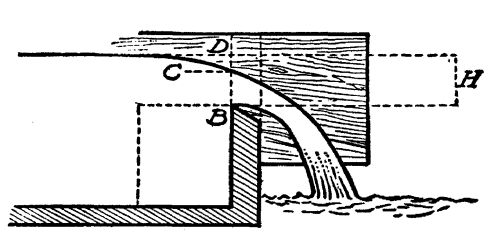
The Simple Weir
Since a steady flow of water, and a constant head, bring about this ideal condition in the water wheel, the first problem that faces the farmer prospector is to determine the amount of water which his stream is capable of delivering. [Pg 38]This is always measured, for convenience, in cubic feet per minute. (A cubic foot of water weighs 62.5 pounds, and contains 7˝ gallons.) This measurement is obtained in several ways, among which probably the use of a weir is the simplest and most accurate, for small streams.
A weir is, in effect, merely a temporary dam set across the stream in such a manner as to form a small pond; and to enable one to measure the water escaping from this pond.
It may be likened to the overflow pipe of a horse trough which is being fed from a spring. To measure the flow of water from such a spring, all that is necessary is to measure the water escaping through the overflow when the water in the trough has attained a permanent level.
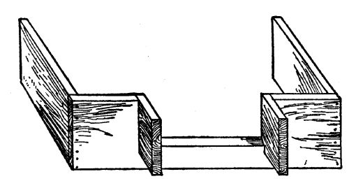 Detail of home-made weir
 Cross-section of weir
The diagrams show the cross-section and detail of a typical weir, which can be put[Pg 39] together in a few minutes with the aid of a saw and hammer. The cross-section shows that the lower edge of the slot through which the water of the temporary pond is made to escape, is cut on a bevel, with its sharp edge upstream. The wing on each side of the opening is for the purpose of preventing the stream from narrowing as it flows through the opening, and thus upsetting the calculations. This weir should be set directly across the flow of the stream, perfectly level, and upright. It should be so imbedded in the banks, and in the bottom of the stream, that no water can escape, except through the opening cut for that purpose. It will require a little experimenting with a rough model to determine just how wide and how deep this opening should be. It should be large enough to prevent water flowing over the top of the[Pg 40] board; and it should be small enough to cause a still-water pond to form for several feet behind the weir. Keep in mind the idea of the overflowing water trough when building your weir. The stream, running down from a higher level behind, should be emptying into a still-water pond, which in turn should be emptying itself through the aperture in the board at the same rate as the stream is keeping the pond full.
Your weir should be fashioned with the idea of some permanency so that a number of measurements may be taken, extending over a period of time—thus enabling the prospector to make a reliable estimate not only of the amount of water flowing at any one time, but of its fluctuations.
Under expert supervision, this simple weir is an exact contrivance—exact enough, in fact, for the finest calculations required in engineering work. To find out how many cubic feet of water the stream is delivering at any moment, all that is necessary is to measure its depth where it flows through the opening. There are[Pg 41] instruments, like the hook-gauge, which are designed to measure this depth with accuracy up to one-thousandth of an inch. An ordinary foot rule, or a folding rule, will give results sufficiently accurate for the water prospector in this instance. The depth should be measured not at the opening itself, but a short distance back of the opening, where the water is setting at a dead level and is moving very slowly.
With this weir, every square inch of water flowing through the opening indicates roughly one cubic foot of water a minute. Thus if the opening is 10 inches wide and the water flowing through it is 5 inches deep, the number of cubic feet a minute the stream is delivering is 10 × 5 = 50 square inches = 50 cubic feet a minute. This is a very small stream; yet, if it could be made to fall through a water wheel 10 feet below a pond or reservoir, it would exert a continuous pressure of 30,000 pounds per minute on the blades of the wheel—nearly one theoretical horsepower.
This estimate of one cubic foot to each square inch is a very rough approximation. Engineers have developed many complicated formulas for determining the flow of water through weirs, taking into account fine variations that the farm prospector need not heed. The so-called Francis formula, developed by a long series of actual experiments at Lowell, Mass., in 1852 by Mr. James B. Francis, with weirs 10 feet long and 5 feet 2 inches high, is standard for these calculations and is expressed (for those who desire to use it for special purposes) as follows:
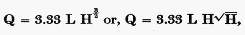
in which Q means quantity of water in cubic feet per second, L is length of opening, in feet; and H is height of opening in feet.
The following table is figured according to the Francis formula, and gives the discharge in cubic feet per minute, for openings one inch wide:
TABLE OF WEIRS
| Inches | 0 | Ľ | ˝ | ľ |
|---|---|---|---|---|
| 1 | 0.403 | 0.563 | 0.740 | 0.966 |
| 2 | 1.141 | 1.360 | 1.593 | 1.838 |
| 3 | 2.094 | 2.361 | 2.639 | 2.927 |
| 4 | 3.225 | 3.531 | 3.848 | 4.173 |
| 5 | 4.506 | 4.849 | 5.200 | 5.558 |
| 6 | 5.925 | 6.298 | 6.681 | 7.071 |
| 7 | 7.465 | 7.869 | 8.280 | 8.697 |
| 8 | 9.121 | 9.552 | 9.990 | 10.427 |
| 9 | 10.884 | 11.340 | 11.804 | 12.272 |
| 10 | 12.747 | 13.228 | 13.716 | 14.208 |
| 11 | 14.707 | 15.211 | 15.721 | 16.236 |
| 12 | 16.757 | 17.283 | 17.816 | 18.352 |
| 13 | 18.895 | 19.445 | 19.996 | 20.558 |
| 14 | 21.116 | 21.684 | 22.258 | 22.835 |
| 15 | 23.418 | 24.007 | 24.600 | 25.195 |
| 16 | 25.800 | 26.406 | 27.019 | 27.634 |
| 17 | 28.256 | 28.881 | 29.512 | 30.145 |
| 18 | 30.785 | 31.429 | 32.075 | 32.733 |
Thus, let us say, our weir has an opening 30 inches wide, and the water overflows through the opening at a uniform depth of 6Ľ inches, when measured a few inches behind the board at a point before the overflow curve begins. Run down the first column on the left to "6", and cross over to the second column to the right, headed "Ľ". This gives the number of cubic feet per minute for this depth one inch wide, as 6.298.[Pg 44] Since the weir is 30 inches wide, multiply 6.298 × 30 = 188.94—or, say, 189 cubic feet per minute.
Once the weir is set, it is the work of but a moment to find out the quantity of water a stream is delivering, simply by referring to the above table.
Another Method of Measuring a Stream
Weirs are for use in small streams. For larger streams, where the construction of a weir would be difficult, the U. S. Geological Survey engineers recommend the following simple method:
Choose a place where the channel is straight for 100 or 200 feet, and has a nearly constant depth and width; lay off on the bank a line 50 or 100 feet in length. Throw small chips into the stream, and measure the time in seconds they take to travel the distance laid off on the bank. This gives the surface velocity of the water. Multiply the average of several such tests by 0.80, which will give very nearly the mean velocity. Then it is[Pg 45] necessary to find the cross-section of the flowing water (its average depth multiplied by width), and this number, in square feet, multiplied by the velocity in feet per second, will give the number of cubic feet the stream is delivering each second. Multiplied by 60 gives cubic feet a minute.
Figuring a Stream's Horsepower
By one of the above simple methods, the problem of Quantity can easily be determined. The next problem is to determine what Head can be obtained. Head is the distance in feet the water may be made to fall, from the Source of Supply, to the water wheel itself. The power of water is directly proportional to head, just as it is directly proportional to quantity. Thus the typical weir measured above was 30 inches wide and 6Ľ deep, giving 189 cubic feet of water a minute—Quantity. Since such a stream is of common occurrence on thousands of farms, let us analyze briefly its possibilities for power: One hundred and eighty-nine cubic feet of water[Pg 46] weighs 189 × 62.5 pounds = 11,812.5 pounds. Drop this weight one foot, and we have 11,812.5 foot-pounds. Drop it 3 feet and we have 11,812 × 3 = 35,437.5 foot-pounds. Since 33,000 foot-pounds exerted in one minute is one horsepower, we have here a little more than one horsepower. For simplicity let us call it a horsepower.
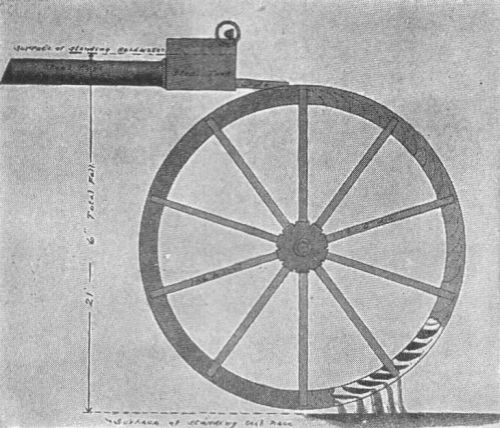
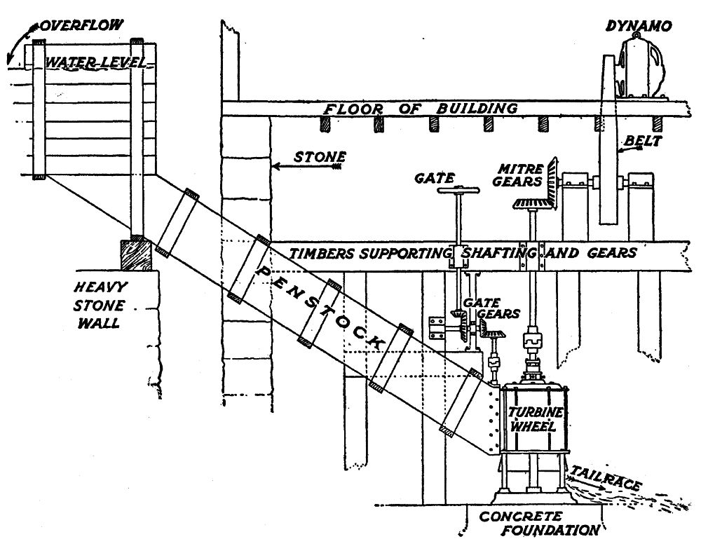 Detail of a water-power plant, showing setting of
wheel, and dynamo connection
Detail of a water-power plant, showing setting of
wheel, and dynamo connection
[Pg 47]Now, since the work to be had from this water varies directly with quantity and head, it is obvious that a stream one-half as big falling twice as far, would still give one horsepower at the wheel; or, a stream of 189 cubic feet a minute falling ten times as far, 30 feet, would give ten times the power, or ten horsepower; a stream falling one hundred times as far would give one hundred horsepower. Thus small quantities of water falling great distances, or large quantities of water falling small distances may accomplish the same results. From this it will be seen, that the simple formula for determining the theoretical horsepower of any stream, in which Quantity and Head are known, is as follows:
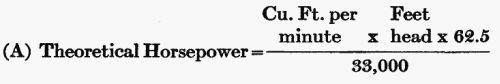
As an example, let us say that we have a stream whose weir measurement shows it capable of delivering 376 cubic feet a minute, with a head (determined by survey) of 13 feet 6 inches. What is the horsepower of this stream?
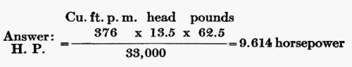
This is theoretical horsepower. To determine the actual horsepower that can be counted on, in practice, it is customary, with small water wheels, to figure 25 per cent loss through friction, etc. In this instance, the actual horsepower would then be 7.2.
The Size of the Wheel
Water wheels are not rated by horsepower by manufacturers, because the same wheel might develop one horsepower or one hundred horsepower, or even a thousand horsepower,[Pg 49] according to the conditions under which it is used. With a given supply of water, the head, in feet, determines the size of wheel necessary. The farther a stream of water falls, the smaller the pipe necessary to carry a given number of gallons past a given point in a given time.
A small wheel, under 10 × 13.5 ft. head, would give the same power with the above 376 cubic feet of water a minute, as a large wheel would with 10 × 376 cubic feet, under a 13.5 foot head.
This is due to the acceleration of gravity on falling bodies. A rifle bullet shot into the air with a muzzle velocity of 3,000 feet a second begins to diminish its speed instantly on leaving the muzzle, and continues to diminish in speed at the fixed rate of 32.16 feet a second, until it finally comes to a stop, and starts to descend. Then, again, its speed accelerates at the rate of 32.16 feet a second, until on striking the earth it has attained the velocity at which it left the muzzle of the rifle, less loss due to friction.
The acceleration of gravity affects falling water in the same manner as it affects a falling bullet. At any one second, during its course of fall, it is traveling at a rate 32.16 feet a second in excess of its speed the previous second.
In figuring the size wheel necessary under given conditions or to determine the power of water with a given nozzle opening, it is necessary to take this into account. The table on page 51 gives velocity per second of falling water, ignoring the friction of the pipe, in heads from 5 to 1000 feet.
The scientific formula from which the table is computed is expressed as follows, for those of a mathematical turn of mind:
Velocity (ft. per sec.) = sqrt(2gh); or, velocity is equal to the square root of the product (g = 32.16,—times head in feet, multiplied by 2).
SPOUTING VELOCITY OF WATER, IN FEET PER SECOND, IN HEADS OF FROM 5 TO 1,000 FEET
| Head | Velocity |
|---|---|
| 5 | 17.9 |
| 6 | 19.7 |
| 7 | 21.2 |
| 8 | 22.7 |
| 9 | 24.1 |
| 10 | 25.4 |
| 11 | 26.6 |
| 11.5 | 27.2 |
| 12 | 27.8 |
| 12.5 | 28.4 |
| 13 | 28.9 |
| 13.5 | 29.5 |
| 14 | 30.0 |
| 14.5 | 30.5 |
| 15 | 31.3 |
| 15.5 | 31.6 |
| 16 | 32.1 |
| 16.5 | 32.6 |
| 17 | 33.1 |
| 17.5 | 33.6 |
| 18 | 34.0 |
| 18.5 | 34.5 |
| 19 | 35.0 |
| 19.5 | 35.4 |
| 20 | 35.9 |
| 20.5 | 36.3 |
| 21 | 36.8 |
| 21.5 | 37.2 |
| 22 | 37.6 |
| 22.5 | 38.1 |
| 23 | 38.5 |
| 23.5 | 38.9 |
| 24 | 39.3 |
| 24.5 | 39.7 |
| 25 | 40.1 |
| 26 | 40.9 |
| 27 | 41.7 |
| 28 | 42.5 |
| 29 | 43.2 |
| 30 | 43.9 |
| 31 | 44.7 |
| 32 | 45.4 |
| 33 | 46.1 |
| 34 | 46.7 |
| 35 | 47.4 |
| 36 | 48.1 |
| 37 | 48.8 |
| 38 | 49.5 |
| 39 | 50.1 |
| 40 | 50.7 |
| 41 | 51.3 |
| 42 | 52.0 |
| 43 | 52.6 |
| 44 | 53.2 |
| 45 | 53.8 |
| 46 | 54.4 |
| 47 | 55.0 |
| 48 | 55.6 |
| 49 | 56.2 |
| 50 | 56.7 |
| 55 | 59.5 |
| 60 | 62.1 |
| 65 | 64.7 |
| 70 | 67.1 |
| 75 | 69.5 |
| 80 | 71.8 |
| 85 | 74.0 |
| 90 | 76.1 |
| 95 | 78.2 |
| 100 | 80.3 |
| 200 | 114.0 |
| 300 | 139.0 |
| 400 | 160.0 |
| 500 | 179.0 |
| 1000 | 254.0 |
In the above example, we found that 376 cubic feet of water a minute, under 13.5 feet head, would deliver 7.2 actual horsepower. Question: What size wheel would it be necessary to install under such conditions?
By referring to the table of velocity above, (or by using the formula), we find that water under a head of 13.5 feet, has a spouting velocity of 29.5 feet a second. This means that a solid stream of water 29.5 feet long would pass through the wheel in one second. What should be the diameter of such a stream, to make its cubical contents 376 cubic feet a minute or 376/60 = 6.27 cubic feet a second? The following formula should be used to determine this:
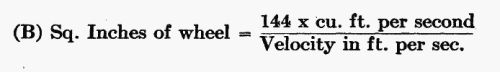
Substituting values, in the above instance, we have:
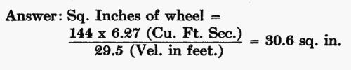
That is, a wheel capable of using 30.6 square inches of water would meet these conditions.
What Head is Required
Let us attack the problem of water-power in another way. A farmer wishes to install a water wheel that will deliver 10 horsepower on the shaft, and he finds his stream delivers 400 cubic feet of water a minute. How many feet fall is required? Formula:
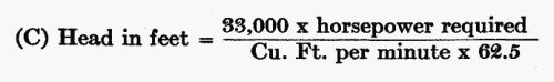
Since a theoretical horsepower is only 75 per cent efficient, he would require 10 × 4/3 = 13.33 theoretical horsepower of water, in this instance. Substituting the values of the problem in the formula, we have:

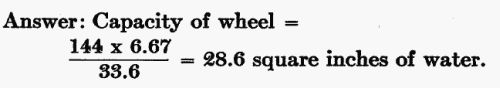
What capacity of wheel would this prospect (400 cubic feet of water a minute falling 17.6 feet, and developing 13.33 horsepower) require?
By referring to the table of velocities, we find that the velocity for 17.5 feet head (nearly) is 33.6 feet a second. Four hundred[Pg 54] feet of water a minute is 400/60 = 6.67 cu. ft. a second. Substituting these values, in formula (B) then, we have:
Quantity of Water
Let us take still another problem which the prospector may be called on to solve: A man finds that he can conveniently get a fall of 27 feet. He desires 20 actual horsepower. What quantity of water will be necessary, and what capacity wheel?
Twenty actual horsepower will be 20 × 4/3 = 26.67 theoretical horsepower. Formula:
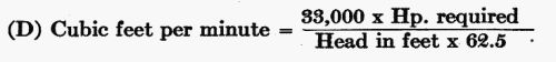
Substituting values, then, we have:
A head of 27 feet would give this stream a velocity of 41.7 feet a second, and, from[Pg 55] formula (B) we find that the capacity of the wheel should be 30 square inches.
It is well to remember that the square inches of wheel capacity does not refer to the size of pipe conveying water from the head to the wheel, but merely to the actual nozzle capacity provided by the wheel itself. In small installations of low head, such as above a penstock at least six times the nozzle capacity should be used, to avoid losing effective head from friction. Thus, with a nozzle of 30 square inches, the penstock or pipe should be 180 square inches, or nearly 14 inches square inside measurement. A larger penstock would be still better.
THE WATER WHEEL AND HOW TO INSTALL IT
Different types of water wheels—The impulse and reaction wheels—The impulse wheel adapted to high heads and small amount of water—Pipe lines—Table of resistance in pipes—Advantages and disadvantages of the impulse wheel—Other forms of impulse wheels—The reaction turbine, suited to low heads and large quantity of water—Its advantages and limitations—Developing a water-power project: the dam; the race; the flume; the penstock; and the tailrace—Water rights for the farmer.
In general, there are two types of water wheels, the impulse wheel and the reaction wheel. Both are called turbines, although the name belongs, more properly, to the reaction wheel alone.
Impulse wheels derive their power from the momentum of falling water. Reaction wheels derive their power from the momentum and pressure of falling water. The old-fashioned undershot, overshot, and breast wheels[Pg 57] are familiar to all as examples of impulse wheels. Water wheels of this class revolve in the air, with the energy of the water exerted on one face of their buckets. On the other hand, reaction wheels are enclosed in water-tight cases, either of metal or of wood, and the buckets are entirely surrounded by water.
The old-fashioned undershot, overshot, and breast wheels were not very efficient; they wasted about 75 per cent of the power applied to them. A modern impulse wheel, on the other hand, operates at an efficiency of 80 per cent and over. The loss is mainly through friction and leakage, and cannot be eliminated altogether. The modern reaction wheel, called the turbine, attains an equal efficiency. Individual conditions govern the type of wheel to be selected.
The Impulse, or Tangential Water Wheel
The modern impulse, or tangential wheel (so called because the driving stream of water strikes the wheel at a tangent) is best adapted to situations where the amount of water is[Pg 58] limited, and the head is large. Thus, a mountain brook supplying only seven cubic feet of water a minute—a stream less than two-and-a-half inches deep flowing over a weir with an opening three inches wide—would develop two actual horsepower, under a head of 200 feet—not an unusual head to be found in the hill country. Under a head of one thousand feet, a stream furnishing 352.6 cubic feet of water a minute would develop 534.01 horsepower at the nozzle.
Ordinarily these wheels are not used under heads of less than 20 feet. A wheel of this type, six feet in diameter, would develop six horsepower, with 188 cubic feet of water a minute and 20-foot head. The great majority of impulse wheels are used under heads of 100 feet and over. In this country the greatest head in use is slightly over 2,100 feet, although in Switzerland there is one plant utilizing a head of over 5,000 feet.
 The Fitz overshoot wheel
The old-fashioned impulse wheels were inefficient because of the fact that their buckets were not constructed scientifically, and much of the force of the water was lost at the moment of impact. The impulse wheel of to-day, however, has buckets which so completely [Pg 59]absorb the momentum of water issuing from a nozzle, that the water falls into the tailrace with practically no velocity. When it is remembered that the nozzle pressure under a 2,250-foot head is nearly 1,000 pounds to the square inch, and that water issues from this nozzle with a velocity of 23,000 feet a minute, the scientific precision of this type of bucket can be appreciated.
A typical bucket for such a wheel is shaped like an open clam shell, the central line which cuts the stream of water into halves being ground to a sharp edge. The curves which absorb the momentum of the water are figured mathematically and in practice become polished like mirrors. So great is the eroding action of water, under great heads—especially when it contains sand or silt—that it is occasionally necessary to replace these buckets. For this reason the larger wheels consist merely of a spider of iron or steel, with each[Pg 60] bucket bolted separately to its circumference, so that it can be removed and replaced easily. Usually only one nozzle is provided; but in order to use this wheel under low heads—down to 10 feet—a number of nozzles are used, sometimes five, where the water supply is plentiful.
The wheel is keyed to a horizontal shaft running in babbited bearings, and this same shaft is used for driving the generator, either by direct connection, or by means of pulleys and a belt. The wheel may be mounted on a home-made timber base, or on an iron frame. It takes up very little room, especially when it is so set that the nozzle can be mounted under the flooring. The wheel itself is enclosed, above the floor, in a wooden box, or a casing made of cast or sheet iron, which should be water-tight.
Since these wheels are usually operated under great heads, the problem of regulating their water supply requires special consideration. A gate is always provided at the upper, or intake end, where the water pipe leaves the[Pg 61] flume. Since the pressure reaches 1,000 pounds the square inch and more, there would be danger of bursting the pipe if the water were suddenly shut off at the nozzle itself. For this reason it is necessary to use a needle valve, similar to that in an ordinary garden hose nozzle; and by such a valve the amount of water may be regulated to a nicety. Where the head is so great that even such a valve could not be used safely, provision is made to deflect the nozzle. These wheels have a speed variation amounting to as much as 25 per cent from no-load to full load, in generating electricity, and since the speed of the prime mover—the water wheel—is reflected directly in the voltage or pressure of electricity delivered, the wheel must be provided with some form of automatic governor. This consists usually of two centrifugal balls, similar to those used in governing steam engines; these are connected by means of gears to the needle valve or the deflector.
As the demand for farm water-powers in our hill sections becomes more general, the[Pg 62] tangential type of water wheel will come into common use for small plants. At present it is most familiar in the great commercial installations of the Far West, working under enormous heads. These wheels are to be had in the market ranging in size from six inches to six feet and over. Wheels ranging in size from six inches to twenty-four inches are called water motors, and are to be had in the market, new, for $30 for the smallest size, and $275 for the largest. Above three feet in diameter, the list prices will run from $200 for a 3-foot wheel to $800 for a 6-foot wheel. Where one has a surplus of water, it is possible to install a multiple nozzle wheel, under heads of from 10 to 100 feet, the cost for 18-inch wheels of this pattern running from $150 to $180 list, and for 24-inch wheels from $200 to $250. A 24-inch wheel, with a 10-foot head would give 1.19 horsepower, enough for lighting the home, and using an electric iron. Under a 100-foot head this same wheel would provide 25.9 horsepower, to meet the requirements of a bigger-than-average farm plant.
The Pipe Line
The principal items of cost in installing an impulse wheel are in connection with the pipe line, and the governor. In small heads, that is, under 100 feet, the expense of pipe line is low. Frequently, however, the governor will cost more than the water motor itself, although cheaper, yet efficient, makes are now being put on the market to meet this objection. In a later chapter, we will take up in detail the question of governing the water wheel, and voltage regulation, and will attempt to show how this expense may be practically eliminated by the farmer.
To secure large heads, it is usually necessary to run a pipe line many hundreds (and in many cases, many thousands) of feet from the flume to the water wheel. Water flowing through pipes is subject to loss of head, by friction, and for this reason the larger the pipe the less the friction loss. Under no circumstances is it recommended to use a pipe of less than two inches in diameter, even for the smallest water[Pg 64] motors; and with a two-inch pipe, the run should not exceed 200 feet. Where heavy-pressure mains, such as those of municipal or commercial water systems, are available, the problem of both water supply and head becomes very simple. Merely ascertain the pressure of the water in the mains when flowing, determine the amount of power required (as illustrated in a succeeding chapter of this book), and install the proper water motor with a suitably sized pipe.
Where one has his own water supply, however, and it is necessary to lay pipe to secure the requisite fall, the problem is more difficult. Friction in pipes acts in the same way as cutting down the head a proportional amount; and by cutting down the head, your water motor loses power in direct proportion to the number of feet head lost. This head, obtained by subtracting friction and other losses from the surveyed head, is called the effective head, and determines the amount of power delivered at the nozzle.
The tables on pages 66-67 show the friction[Pg 65] loss in pipes up to 12 inches in diameter, according to the amount of water, and the length of pipe.
In this example it is seen that a 240-foot static head is reduced by friction to 230.1 feet effective head. By referring to the table we find the wheel fitting these conditions has a nozzle so small that it cuts down the rate of flow of water in the big pipe to 4.4 feet a second, and permits the flow of only 207 cubic feet of water a minute. The actual horsepower of this tube and nozzle, then, can be figured by applying formula (A), Chapter III, allowing 80 per cent for the efficiency of the wheel. Thus:
To calculate what the horsepower of this tube 12 inches in diameter and 900 feet long, would be without a nozzle, under a head of 240 feet, introduces a new element of friction losses, which is too complicated to figure here. Such a condition would not be met[Pg 66] with in actual practice, in any event. The largest nozzles used, even in the jumbo plants of the Far West, rarely exceed 10 inches in diameter; and the pipe conveying water to such a nozzle is upwards of eight feet in diameter.
PIPE FRICTION TABLES
INDICATING THE CALCULATED LOSS OF HEAD DUE TO FRICTION IN RIVETED STEEL PIPE WITH VARIOUS WATER QUANTITIES AND VELOCITIES
[Courtesy of the Pelton Water Wheel Company]
Heavy-faced figures = Loss of head in feet for each one thousand feet
of pipe.
Light-faced figures = Water quantity in cubic feet per minute.
| Pipe Diameter | Velocity in Feet per Second | ||||||||||||
| 2.0 | 2.2 | 2.4 | 2.6 | 2.8 | 3.0 | 3.2 | 3.4 | 3.6 | 3.8 | 4.0 | 4.2 | 4.4 | |
| 17.1 | 20.0 | 25.6 | 28.3 | 32.0 | 37.3 | 40.9 | 45.8 | 50.4 | 56.0 | 62.3 | 68.1 | 74.9 | |
| 3" | 5.9 | 6.5 | 7.1 | 7.7 | 8.3 | 8.9 | 9.4 | 10.0 | 10.6 | 11.2 | 11.8 | 12.4 | 13.0 |
| 11.0 | 13.0 | 15.0 | 17.3 | 20.2 | 23.2 | 26.2 | 29.6 | 33.0 | 36.5 | 41.0 | 45.4 | 49.2 | |
| 4" | 10.5 | 11.5 | 12.6 | 13.6 | 14.7 | 15.7 | 16.8 | 17.8 | 18.8 | 19.9 | 21.0 | 22.0 | 23.0 |
| 7.7 | 9.4 | 11.0 | 12.9 | 14.9 | 16.9 | 19.5 | 21.6 | 24.0 | 27.0 | 29.8 | 32.9 | 36.0 | |
| 5" | 16.4 | 18.0 | 19.6 | 21.2 | 22.9 | 24.5 | 26.1 | 27.8 | 29.5 | 31.0 | 32.7 | 34.3 | 36.0 |
| 6.0 | 7.2 | 8.6 | 9.9 | 11.7 | 13.0 | 14.6 | 16.6 | 19.0 | 21.5 | 23.4 | 25.5 | 27.8 | |
| 6" | 23.5 | 25.9 | 28.2 | 30.6 | 32.9 | 35.3 | 37.7 | 40.0 | 42.4 | 44.7 | 47.1 | 49.5 | 51.8 |
| 4.9 | 6.9 | 7.0 | 8.1 | 9.3 | 10.6 | 12.0 | 13.6 | 15.2 | 17.0 | 19.0 | 21.0 | 23.0 | |
| 7" | 32.0 | 35.3 | 38.5 | 41.7 | 44.9 | 48.1 | 51.3 | 54.5 | 57.7 | 60.9 | 64.1 | 67.3 | 70.5 |
| 4.0 | 4.9 | 6.0 | 6.9 | 7.8 | 9.1 | 10.0 | 10.2 | 13.0 | 14.4 | 15.9 | 17.2 | 19.2 | |
| 8" | 41.9 | 46.1 | 50.2 | 54.4 | 58.6 | 62.8 | 67.0 | 71.2 | 75.4 | 79.6 | 83.7 | 87.9 | 92.1 |
| 3.4 | 4.2 | 5.1 | 5.9 | 6.7 | 7.7 | 8.9 | 9.8 | 11.0 | 12.2 | 13.8 | 15.0 | 16.0 | |
| 9" | 53.0 | 58.3 | 63.6 | 68.9 | 74.2 | 79.5 | 84.8 | 90.1 | 95.4 | 101 | 106 | 111 | 116 |
| 2.9 | 3.7 | 4.4 | 5.1 | 5.9 | 6.7 | 7.5 | 8.6 | 9.5 | 10.6 | 12.1 | 13.1 | 14.1 | |
| 10" | 65.4 | 72.0 | 78.5 | 85.1 | 91.6 | 98.2 | 105 | 111 | 118 | 124 | 131 | 137 | 144 |
| 2.6 | 3.2 | 3.8 | 4.4 | 5.1 | 5.9 | 6.6 | 7.5 | 8.4 | 9.5 | 10.3 | 10.1 | 12.5 | |
| 11" | 79 | 87 | 95 | 103 | 111 | 119 | 127 | 134 | 142 | 150 | 158 | 166 | 174 |
| 2.36 | 2.9 | 3.4 | 3.9 | 4.5 | 5.2 | 5.9 | 6.7 | 7.5 | 8.5 | 9.4 | 10.0 | 11.0 | |
| 12" | 94 | 103 | 113 | 122 | 132 | 141 | 151 | 160 | 169 | 179 | 188 | 198 | 207 |
| Pipe Diameter | Velocity in Feet per Second | |||||||||||
| 4.6 | 4.8 | 5.0 | 5.2 | 5.4 | 5.6 | 5.8 | 6.0 | 7.0 | 8.0 | 9.0 | 10.0 | |
| 78.1 | 82.0 | 89.5 | 98.9 | 105.0 | 113.2 | 120.8 | 130.0 | 162.8 | 216.0 | 270. | 323. | |
| 3" | 13.6 | 14.2 | 14.8 | 15.3 | 15.9 | 16.5 | 17.1 | 17.7 | 20.6 | 23.5 | 26.5 | 29.5 |
| 52.3 | 57.0 | 61.5 | 68.0 | 72.5 | 78.2 | 83.1 | 89.5 | 121. | 155. | 198. | 242. | |
| 4" | 24.1 | 25.1 | 26.2 | 27.2 | 28.3 | 29.3 | 30.4 | 31.5 | 36.6 | 41.9 | 47.2 | 52.4 |
| 39.2 | 42.3 | 46.0 | 49.8 | 53.5 | 58.0 | 62.0 | 67.0 | 89. | 118. | 148. | 182. | |
| 5" | 37.6 | 39.2 | 40.9 | 42.5 | 44.1 | 45.8 | 47.5 | 49.1 | 57.1 | 65.4 | 73.7 | 82.0 |
| 30.6 | 33.1 | 35.6 | 39.0 | 41.6 | 44.6 | 48.0 | 51.6 | 69.0 | 89.0 | 114. | 140. | |
| 6" | 54.1 | 56.5 | 58.9 | 61.2 | 63.6 | 65.9 | 68.3 | 70.7 | 82.4 | 94.3 | 106 | 118 |
| 25.1 | 27.3 | 29.5 | 32.0 | 34.5 | 37.1 | 40.0 | 43.0 | 58.0 | 75.0 | 95.0 | 116. | |
| 7" | 73.7 | 76.9 | 80.2 | 83.3 | 86.6 | 89.8 | 93.0 | 96.2 | 112 | 128 | 145 | 161 |
| 20.0 | 22.5 | 24.9 | 27.0 | 28.8 | 30.6 | 32.8 | 35.5 | 47.5 | 61.2 | 78.6 | 95.1 | |
| 8" | 96.3 | 101 | 105 | 109 | 113 | 117 | 121 | 125 | 146 | 168 | 189 | 210 |
| 17.1 | 19.2 | 21.0 | 22.9 | 24.6 | 26.2 | 28.0 | 30.1 | 40.1 | 52.1 | 66.6 | 82.0 | |
| 9" | 122 | 127 | 132 | 138 | 143 | 148 | 154 | 159 | 185 | 212 | 238 | 265 |
| 14.8 | 16.7 | 17.9 | 19.9 | 21.0 | 22.7 | 24.3 | 25.9 | 34.8 | 45.9 | 58.0 | 70.1 | |
| 10" | 150 | 157 | 163 | 170 | 177 | 183 | 190 | 196 | 229 | 261 | 295 | 327 |
| 13.0 | 14.7 | 15.9 | 17.1 | 18.2 | 20.1 | 21.3 | 22.6 | 30.7 | 40.0 | 50.8 | 62.0 | |
| 11" | 182 | 190 | 198 | 206 | 214 | 222 | 229 | 237 | 277 | 316 | 356 | 396 |
| 11.6 | 13.0 | 14.0 | 15.1 | 16.1 | 17.8 | 19.1 | 20.2 | 27.1 | 35.9 | 45.4 | 55.9 | |
| 12" | 217 | 226 | 235 | 245 | 254 | 264 | 273 | 283 | 330 | 377 | 425 | 472 |
EXAMPLE
Assume the surveyed head as 240 feet, the water quantity as 207 cubic feet per minute and a pipe line 12 inches in diameter 900 feet long. To ascertain the friction loss, refer to column of pipe diameter and follow across the column for 12 inches diameter to the quantity, 207 cubic feet per minute. The heavy-faced figures above 207 indicate that the loss per 1000 feet of pipe length is 11 feet. Therefore, since the pipe in the example is 900 feet long, the loss will be 11.' × 900/1000 or 9.9 feet, and the effective head will be 240' - 9.9' = 230.1'
Steel tubing for supply pipes, from 3 to 12 inches in diameter is listed at from 20 cents to $1.50 a foot, according to the diameter and thickness of the material. Discounts on these prices will vary from 25 to 50 per cent. The farmer can cut down the cost of this pipe by conveying his supply water from its natural source to a pond, by means of an open race, or a wooden flume. An ingenious mechanic can even construct his own pipe out of wood, though figuring labor and materials, it is doubtful if anything would be saved over a riveted steel pipe, purchased at the regular price. This pipe, leading from the pond, or forebay, to the water wheel, should be kept as short as possible; at the same time, the fall should not be too sharp. An angle of 30° will be found very satisfactory, [Pg 69]although pipe is frequently laid at angles up to 50°.
Other Types of Impulse Wheels
In recent years more efficient forms of the old-fashioned overshoot, pitch-back breast, and undershoot wheels have been developed, by substituting steel or other metal for wood, and altering the shape of the buckets to make better use of the power of falling water.
In some forms of overshoot wheels, an efficiency of over 90 per cent is claimed by manufacturers; and this type offers the additional advantage of utilizing small quantities of water, as well as being efficient under varying quantities of water. They utilize the falling weight of water, although by giving the water momentum at the point of delivery, by means of the proper fall, impulse too is utilized in some measure. The modern steel overshoot wheel receives water in its buckets from a spout set a few degrees back of dead center; and its buckets are so shaped that the water is retained a full half-revolution [Pg 70]of the wheel. The old-style overshoot wheel was inefficient principally because the buckets began emptying themselves at the end of a quarter-revolution. Another advantage claimed for these wheels over the old style is that, being made of thin metal, their buckets attain the temperature of the water itself, thus reducing the danger of freezing to a minimum. They are manufactured in sizes from 6 feet in diameter to upwards of fifty feet; and with buckets of from 6 inches to 10 feet in width. In practice it is usual to deliver water to the buckets by means of a trough or pipe, through a suitable spout and gate, at a point two feet above the crown of the wheel. For this reason, the diameter of the wheel corresponds very closely to the head in feet.
The Reaction Turbine
The reaction turbine is best adapted to low heads, with a large supply of water. It is not advisable, under ordinary circumstances, to use it under heads exceeding 100 feet, as[Pg 71] its speed is then excessive. It may be used under falls as low as two feet. Five thousand cubic feet of water a minute would give approximately 14 actual horsepower under such a head. A sluggish creek that flows in large volume could thus be utilized for power with the reaction turbine, whereas it would be useless with an impulse wheel. Falls of from five to fifteen feet are to be found on thousands of farm streams, and the reaction turbine is admirably adapted to them.
Reaction turbines consist of an iron "runner" which is in effect a rotary fan, the pressure and momentum of the column of water pressing on the slanted blades giving it motion and power. These wheels are manufactured in a great variety of forms and sizes; and are to be purchased either as the runner (set in bearings) alone, or as a runner enclosed in an iron case. In case the runner alone is purchased, the owner must enclose it, either with iron or wood. They vary in price according to size, and the means by which the flow of water is controlled. A simple 12-inch reaction[Pg 72] turbine wheel, such as would be suitable for many power plants can be had for $75. A twelve-inch wheel, using 18 or 20 square inches of water, would generate about 7˝ horsepower under a 20-foot head, with 268 cubic feet of water a minute. Under a 30-foot head, and with 330 cubic feet of water such a wheel will give 14 horsepower. A 36-inch wheel, under a 5-foot head, would use 2,000 cubic feet of water, and give 14 horsepower. Under a 30-foot head, this same wheel, using 4,900 cubic feet of water a minute, would develop over 200 horsepower. If the farmer is confronted by the situation of a great deal of water and small head, a large wheel would be necessary. Thus he could secure 35 horsepower with only a 3-foot head, providing his water supply is equal to the draft of 8,300 cubic feet a minute.
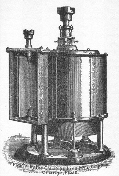 A typical vertical turbine
From these sample figures, it will be seen that the reaction turbine will meet the requirements of widely varying conditions up to, say a head of 100 feet. The farmer prospector should measure first the quantity of water to be depended on, and then the number of feet fall to be had. [Pg 74]The higher the fall, with certain limits, the smaller the expense of installation, and the less water required. When he has determined quantity and head, the catalogue of a reputable manufacturer will supply him with what information is necessary to decide on the style and size wheel he should install. In the older settled communities, especially in New England, a farmer should be able to pick up a second-hand turbine, at half the price asked for a new one; and since these wheels do not depreciate rapidly, it would serve his purpose as well, in most cases, as a new one.
Reaction turbines may be either horizontal or vertical. If they are vertical, it is necessary to connect them to the main shaft by means of a set of bevel gears. These gears should be substantially large, and if the teeth are of hard wood (set in such a manner that they can be replaced when worn) they will be found more satisfactory than if of cast or cut metal.
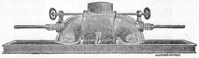 Two wheels on a horizontal shaft
The horizontal turbine is keyed to its shaft, like the impulse wheel, so that the wheel shaft itself is used for driving, without gears or a quarter-turn belt. (The latter is to be avoided, wherever possible.) There are many forms of horizontal turbines; they are to be had of the duplex type, that is, two wheels on one shaft. These are arranged so that either wheel may be run separately, or both together, thus permitting one to take advantage of the seasonal fluctuation in water supply. A convenient form of these wheels includes draft tubes, by which the wheel may be set several feet above the tailrace, and the advantage of this additional fall still be preserved. In this case the draft tube must be airtight so as to form suction, when[Pg 76] filled with escaping water, and should be proportioned to the size of the wheel. Theoretically these draft tubes might be 34 feet long, but in practice it has been found that they should not exceed 10 or 12 feet under ordinary circumstances. They permit the wheel to be installed on the main floor of the power station, with the escape below, instead of being set just above the tailrace level itself, as is the case when draft tubes are not used.
Reaction turbines when working under a variable load require water governors (like impulse wheels) although where the supply of water is large, and the proportion of power between water wheel and dynamo is liberal—say two to one, or more—this necessity is greatly reduced. Reaction wheels as a rule govern themselves better than impulse wheels, due both to the fact that they use more water, and that they operate in a small airtight case. The centrifugal ball governor is the type usually used with reaction wheels as well as with impulse wheels. This subject will be discussed more fully later.
Installing a Power Plant
In developing a power prospect, the dam itself is usually not the site of the power plant. In fact, because of danger from flood water and ice, it is better to locate it in a more protected spot, leading the water to the wheel by means of a race and flume.
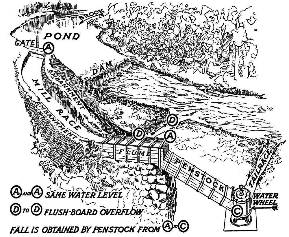 Bird's-eye view of a developed water-power plant
A typical crib dam, filled with stone, is shown in section in the diagram, and the half-tone illustration shows such a dam in course of construction. The first bed of timbers should be laid on hard-pan or[Pg 78] solid rock in the bed of the stream parallel to its flow. The second course, across the stream, is then begun, being spiked home by means of rods cut to length and sharpened by the local blacksmith, from ľ-inch Norway iron. Hemlock logs are suitable for building the crib; and as the timbers are finally laid, it should be filled in and made solid with boulders. This filling in should proceed section by section, as the planking goes forward, otherwise there will be no escape for the water of the stream, until it rises and spills over the top timbers. The planking should be of two-inch[Pg 79] chestnut, spiked home with 60 penny wire spikes. When the last section of the crib is filled with boulders and the water rises, the remaining planks may be spiked home with the aid of an iron pipe in which to drive the spike by means of a plunger of iron long enough to reach above the level of the water. When the planking is completed, the dam should be well gravelled, to within a foot or two of its crest. Such dams are substantial, easily made with the aid of unskilled labor, and the materials are to be had on the average farm with the exception of the hardware.
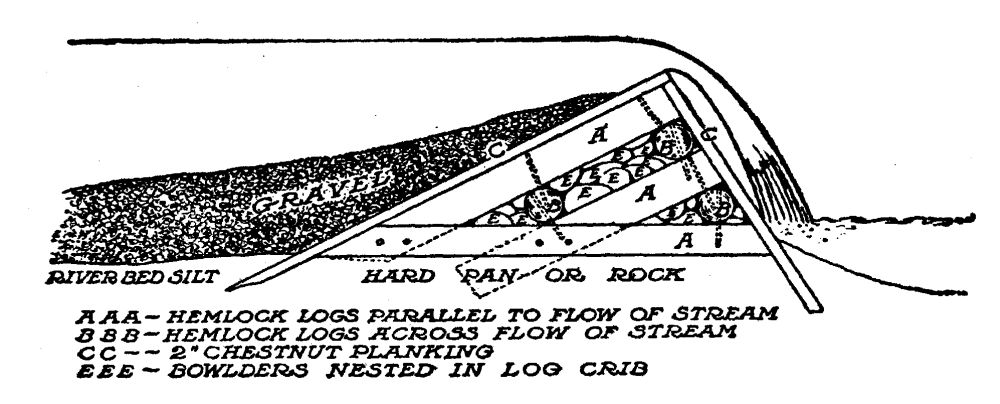 Cross-section of a rock and timber dam
This dam forms a pond from which the race[Pg 80] draws its supply of water for the wheel. It also serves as a spillway over which the surplus water escapes. The race should enter the pond at some convenient point, and should be protected at or near its point of entrance by a bulkhead containing a gate, so that the supply of water may be cut off from the race and wheel readily. The lay of the land will determine the length and course of the race. The object of the race is to secure the required head by carrying a portion of the available water to a point where it can escape, by a fall of say 30° to the tailrace. It may be feasible to carry the race in a line almost at right angles to the stream itself, or, again, it may be necessary to parallel the stream. If the lay of the land is favorable, the race may be dug to a distance of a rod or so inshore, and then be permitted to cut its own course along the bank, preventing the water escaping back to the river or brook before the site of the power plant is reached, by building suitable retaining embankments. The race should be of ample size for conveying the water required[Pg 81] without too much friction. It should end in a flume constructed stoutly of timbers. It is from this flume that the penstock draws water for the wheel. When the wheel gate is closed the water in the mill pond behind the dam, and in the flume itself should maintain an approximate level. Any surplus flow is permitted to escape over flushboards in the flume; these same flushboards maintain a constant head when the wheel is in operation by carrying off what little surplus water the race delivers from the pond.
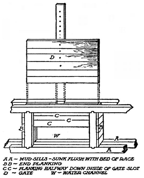 Detail of bulkhead gate
At some point in the race or flume, the flow should be protected from leaves and other trash by means of a rack. This rack is best made of Ľ or[Pg 82] ˝-inch battens from 1˝ to 3 inches in width, bolted together on their flat faces and separated a distance equal to the thickness of the battens by means of iron washers. This rack will accumulate leaves and trash, varying with the time of year and should be kept clean, so as not to cut down the supply of water needed by the wheel.
The penstock, or pipe conveying water from the flume to the wheel, should be constructed of liberal size, and substantially, of two-inch chestnut planking, with joints caulked with oakum, and the whole well bound together to resist the pressure of the water. Means should be provided near the bottom for an opening through which to remove any obstructions that may by accident pass by the rack. Many wheels have plates provided in their cases for this purpose.
The tailrace should be provided with enough fall to carry the escaping water back to the main stream, without backing up on the wheel itself and thus cutting down the head.
It is impossible to make any estimates of the[Pg 83] cost of such a water-power plant. The labor required will in most instances be supplied by the farmer himself, his sons, and his help, during times when farm operations are slack.
Water Rights of the Farmer
The farmer owns the bed of every stream not navigable, lying within the boundary lines of the farm; and his right to divert and make use of the water of such streams is determined in most states by common law. In the dry-land states where water is scarce and is valuable for irrigation, a special set of statutes has sprung up with the development of irrigation in this country.
A stream on the farm is either public or private; its being navigable or "floatable" (suitable for floating logs) determining which. Water rights are termed in law "riparian" rights, and land is riparian only when water flows over it or along its borders.
Green (Law for the American Farmer) says:
"Water is the common and equal property of every one through whose land it flows,[Pg 84] and the right of each land-owner to use and consume it without destroying, or unreasonably impairing the rights of others, is the same. An owner of land bordering on a running stream has the right to have its waters flow naturally, and none can lawfully divert them without his consent. Each riparian proprietor has an equal right with all the others to have the stream flow in its natural way without substantial reduction in volume, or deterioration in quality, subject to a proper and reasonable use of its waters for domestic, agricultural and manufacturing purposes, and he is entitled to use it himself for such purposes, but in doing so must not substantially injure others. In addition to the right of drawing water for the purposes just mentioned, a riparian proprietor, if he duly regards the rights of others, and does not unreasonably deplete the supply, has also the right to take the water for some other proper uses."
Thus, the farmer who seeks to develop water-power from a stream flowing across his own[Pg 85] land, has the right to divert such a stream from its natural channel—providing it is not a navigable or floatable stream—but in so doing, he must return it to its own channel for lower riparian owners. The generation of water-power does not pollute the water, nor does it diminish the water in quantity, therefore the farmer is infringing on no other owner's rights in using the water for such a purpose.
When a stream is a dividing line between two farms, as is frequently the case, each proprietor owns to the middle of the stream and controls its banks. Therefore to erect a dam across such a private stream and divert all or a part of the water for power purposes, requires the consent of the neighboring owner. The owner of the dam is responsible for damage due to flooding, to upstream riparian owners.
ELECTRICITY
THE DYNAMO; WHAT IT DOES, AND HOW
Electricity compared to the heat and light of the Sun—The simple dynamo—The amount of electric energy a dynamo will generate—The modern dynamo—Measuring power in terms of electricity—The volt—The ampere—The ohm—The watt and the kilowatt—Ohm's Law of the electric circuit, and some examples of its application—Direct current, and alternating current—Three types of direct-current dynamos: series, shunt, and compound.
What a farmer really does in generating electricity from water that would otherwise run to waste in his brook, is to install a private Sun of his own—which is on duty not merely in daylight, but twenty-four hours a day; a private Sun which is under such simple control that it shines or provides heat and power, when and where wanted, simply by touching a button.
This is not a mere fanciful statement. When you come to look into it you find that[Pg 90] electricity actually is the life-giving power of the Sun's rays, so transformed that it can be handily conveyed from place to place by means of wires, and controlled by mechanical devices as simple as the spigot that drains a cask.
Nature has the habit of traveling in circles. Sometimes these circles are so big that the part of them we see looks like a straight line, but it is not. Even parallel lines, according to the mathematicians, "meet in infinity." Take the instance of the water wheel which the farmer has installed under the fall of his brook. The power which turns the wheel has the strength of many horses. It is there in a handy place for use, because the Sun brought it there. The Sun, by its heat, lifted the water from sea-level, to the pond where we find it—and we cannot get any more power out of this water by means of a turbine using its pressure and momentum in falling, than the Sun itself expended in raising the water against the force of gravity.
Once we have installed the wheel to change the energy of falling water into mechanical[Pg 91] power, the task of the dynamo is to turn this mechanical power into another mode of motion—electricity. And the task of electricity is to change this mode of motion back into the original heat and light of the Sun—which started the circle in the beginning.
Astronomers refer to the Sun as "he" and "him" and they spell his name with a capital letter, to show that he occupies the center of our small neighborhood of the universe at all times.
Magnets and Magnetism
The dynamo is a mechanical engine, like the steam engine, the water turbine or the gas engine; and it converts the mechanical motion of the driven wheel into electrical motion, with the aid of a magnet. Many scientists say that the full circle of energy that keeps the world spinning, grows crops, and paints the sky with the Aurora Borealis, begins and ends with magnetism—that the sun's rays are magnetic rays. Magnetism is the force that keeps the compass needle pointing north[Pg 92] and south. Take a steel rod and hold it along the north and south line, slightly inclined towards the earth, and strike it a sharp blow with a hammer, and it becomes a magnet—feeble, it is true, but still a magnet.
Take a wire connected with a common dry battery and hold a compass needle under it and the needle will immediately turn around and point directly across the wire, showing that the wire possesses magnetism encircling it in invisible lines, stronger than the magnetism of the earth.
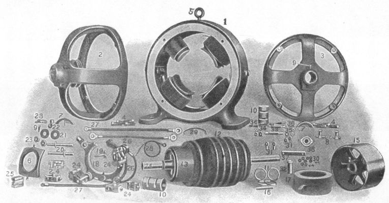 A direct-current dynamo or motor, showing details of construction
Insulate this wire by covering it with cotton thread, and wind it closely on a spool. Connect the two loose ends to a dry battery, and you will find that you have multiplied the magnetic strength of a single loop of wire by the number of turns on the spool—concentrated all the magnetism of the length of that wire into a small space. Put an iron core in the middle of this spool and the magnet seems still more powerful. Lines of force which otherwise would escape in great circles into space, are now concentrated in the iron. The iron core is a magnet. Shut off the current from the battery and the iron is still a magnet—weak, true, but it will always retain a[Pg 93] small portion of its magnetism. Soft iron retains very little of its magnetism. Hard steel retains a great deal, and for this reason steel is used for permanent magnets, of the horseshoe type so familiar.
A Simple Dynamo
A dynamo consists, first, of a number of such magnets, wound with insulated wire. Their iron cores point towards the center of a circle like the spokes of a wheel; and their curved inner faces form a circle in which a spool, wound with wire in another way, may be spun by the water wheel.
Now take a piece of copper wire and make a loop of it. Pass one side of this loop in front of an electric magnet.
As the wire you hold in your hands passes the iron face of the magnet, a wave of energy that is called electricity flows around this loop at the rate of 186,000 miles a second—the[Pg 94] same speed as light comes to us from the sun. As you move the wire away from the magnet, a second wave starts through the wire, flowing in the opposite direction. You can prove this by holding a compass needle under the wire and see it wag first in one direction, then in another.
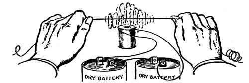 A wire "cutting" the lines of force of an
electro-magnet
A wire "cutting" the lines of force of an
electro-magnet
This is a simple dynamo. A wire "cutting" the invisible lines of force, that a magnet is spraying out into the air, becomes "electrified." Why this is true, no one has ever been able to explain.
The amount of electricity—its capacity for work—which you have generated with the magnet and wire, does not depend alone on the pulling power of that simple magnet. Let us say the magnet is very weak—has not enough power to lift one ounce of iron. Nevertheless, [Pg 95]if you possessed the strength of Hercules, and could pass that wire through the field of force of the magnet many thousands of times a second, you would generate enough electricity in the wire to cause the wire to melt in your hands from heat.
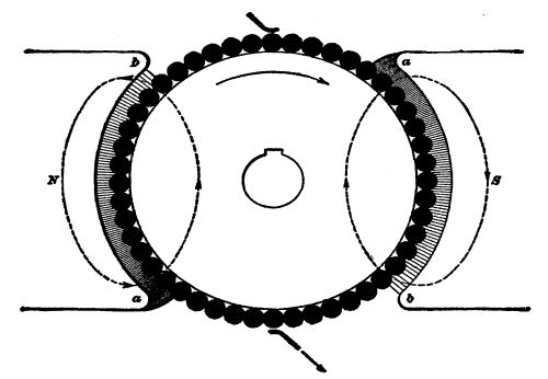 Cross-section of an armature revolving in its field
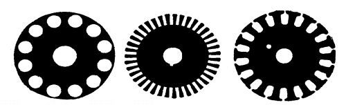 Forms of annealed steel discs used in armature
construction
Forms of annealed steel discs used in armature
construction
This experiment gives the theory of the dynamo. Instead of passing only one wire through the field of force of a magnet, we have hundreds bound lengthwise on a revolving drum called an armature. Instead of one magnetic pole in a dynamo we have two, or[Pg 96] four, or twenty according to the work the machine is designed for—always in pairs, a North pole next to a South pole, so that the lines of force may flow out of one and into another, instead of escaping in the surrounding air. If you could see these lines of force, they would appear in countless numbers issuing from each pole face of the field magnets, pressing against the revolving drum like hair brush bristles—trying to hold it back. This drum, in practice, is built up of discs of annealed steel, and the wires extending lengthwise on its face are held in place by slots to prevent them from flying off when the drum is whirled at high speed. The drum does not touch the face of the magnets, but revolves in an air space. If we give the electric impulses generated in these wires a chance to flow in a[Pg 97] circuit—flow out of one end of the wires, and in at the other, the drum will require more and more power to turn it, in proportion to the amount of electricity we permit to flow. Thus, if one electric light is turned on, the drum will press back with a certain strength on the water wheel; if one hundred lights are turned on it will press back one hundred times as much. Providing there is enough power in the water wheel to continue turning the drum at its predetermined speed, the dynamo will keep on giving more and more electricity if asked to, until it finally destroys itself by fire. You cannot take more power, in terms of electricity, out of a dynamo that you put into it, in terms of mechanical motion. In fact,[Pg 98] to insure flexibility and constant speed at all loads, it is customary to provide twice as much water wheel, or engine, power as the electrical rating of the dynamo.
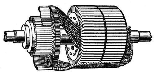 An armature partly wound, showing slots and commutator
We have seen that a water wheel is 85 per cent efficient under ideal conditions. A dynamo's efficiency in translating mechanical motion into electricity, varies with the type of machine and its size. The largest machines attain as high as 90 per cent efficiency; the smallest ones run as low as 40 per cent.
Measuring Electric Power
The amount of electricity any given dynamo can generate depends, generally speaking, on two factors, i. e., (1) the power of the water wheel, or other mechanical engine that turns the armature; and (2) the size (carrying capacity) of the wires on this drum.
Strength, of electricity, is measured in amperes. An ampere of electricity is the unit of the rate of flow and may be likened to a gallon of water per minute.
In surveying for water-power, in Chapter[Pg 99] III, we found that the number of gallons or cubic feet of water alone did not determine the amount of power. We found that the number of gallons or cubic feet multiplied by the distance in feet it falls in a given time, was the determining factor—pounds (quantity) multiplied by feet per second—(velocity).
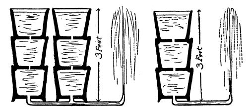 Showing the analogy of water to volts and amperes of
electricity
Showing the analogy of water to volts and amperes of
electricity
The same is true in figuring the power of electricity. We multiply the amperes by the number of electric impulses that are created in the wire in the course of one second. The unit of velocity, or pressure of the electric current is called a volt. Voltage is the pressure which causes electricity to flow. A volt may be likened to the velocity in feet per second of water in falling past a certain point. If you[Pg 100] think a moment you will see that this has nothing to do with quantity. A pin-hole stream of water under 40 pounds pressure has the same velocity as water coming from a nozzle as big as a barrel, under the same pressure. So with electricity under the pressure of one volt or one hundred volts.
One volt is said to consist of a succession of impulses caused by one wire cutting 100,000,000 lines of magnetic force in one second. Thus, if the strength of a magnet consisted of one line of force, to create the pressure of one volt we would have to "cut" that line of force 100,000,000 times a second, with one wire; or 100,000 times a second with one thousand wires. Or, if a magnet could be made with 100,000,000 lines of force, a single wire cutting those lines once in a second would create one volt pressure. In actual practice, field magnets of dynamos are worked at densities up to and over 100,000 lines of force to the square inch, and armatures contain several hundred conductors to "cut" these magnetic lines. The voltage then depends on the speed at[Pg 101] which the armature is driven. In machines for isolated plants, it will be found that the speed varies from 400 revolutions per minute, to 1,800, according to the design of dynamo used.
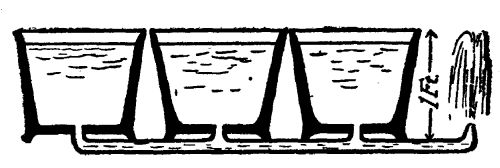 Pressure determines volume of flow in a given time
Multiplying amperes (strength) by volts (pressure), gives us watts (power). Seven hundred and forty-six watts of electrical energy is equal to one horsepower of mechanical energy—will do the same work. Thus an electric current under a pressure of 100 volts, and a density of 7.46 amperes, is one horsepower; as is 74.6 amperes, at 10 volts pressure; or 746 amperes at one volt pressure. For convenience (as a watt is a small quantity) electricity is measured in kilowatts, or 1,000 watts. Since 746 watts is one horsepower, 1,000 watts or one kilowatt is 1.34 horsepower. The work of such a current for one hour is called a kilowatt-hour, and in our cities, where electricity is generated from steam, the retail[Pg 102] price of a kilowatt-hour varies from 10 to 15 cents.
Now as to how electricity may be controlled, so that a dynamo will not burn itself up when it begins to generate.
Again we come back to the analogy of water. The amount of water that passes through a pipe in any given time, depends on the size of the pipe, if the pressure is maintained uniform. In other words the resistance of the pipe to the flow of water determines the amount. If the pipe be the size of a pin-hole, a very small amount of water will escape. If the pipe is as big around as a barrel, a large amount will force its way through. So with electricity. Resistance, introduced in the electric circuit, controls the amount of current that flows. A wire as fine as a hair will permit only a small quantity to pass, under a given pressure. A wire as big as one's thumb will permit a correspondingly greater quantity to pass, the pressure remaining the same. The unit of electrical resistance is called the ohm—named after a man, as are all electrical units.
Ohm's Law
The ohm is that amount of resistance that will permit the passage of one ampere, under the pressure of one volt. It would take two volts to force two amperes through one ohm; or 100 volts to force 100 amperes through the resistance of one ohm. From this we have Ohm's Law, a simple formula which is the beginning and end of all electric computations the farmer will have to make in installing his water-power electric plant. Ohm's Law tells us that the density of current (amperes) that can pass through a given resistance in ohms (a wire, a lamp, or an electric stove) equals volts divided by ohms—or pressure divided by resistance. This formula may be written in three ways, thus:
Or to express the same thing in words, current equals volts divided by ohms; ohms equals volts divided by current; or volts equals current multiplied by ohms. So, with any two of these three determining factors known, we can find the third.[Pg 104] As we have said, this simple law is the beginning and end of ordinary calculations as to electric current, and it should be thoroughly understood by any farmer who essays to be his own electrical engineer. Once understood and applied, the problem of the control of the electric current becomes simple a b c.
Examples of Ohm's Law
Let us illustrate its application by an example. The water wheel is started and is spinning the dynamo at its rated speed, say 1,500 r.p.m. Two heavy wires, leading from brushes which collect electricity from the revolving armature, are led, by suitable insulated supports to the switchboard, and fastened there. They do not touch each other. Dynamo mains must not be permitted to touch each other under any conditions. They are separated by say four inches of air. Dry air is a very poor conductor of electricity. Let us say, for the example, that dry air has a resistance to the flow of an electric current, of 1,000,000 ohms to the inch—that would be[Pg 105] 4,000,000 ohms. How much electricity is being permitted to escape from the armature of this 110-volt dynamo, when the mains are separated by four inches of dry air? Apply Ohm's law, C equals E divided by R. E, in this case is 110; R is 4,000,000; therefore C (amperes) equals 110/4,000,000—an infinitesimal amount—about .0000277 ampere.
Let us say that instead of separating these two mains by air we separated them by the human body—that a man took hold of the bare wires, one in each hand. The resistance of the human body varies from 5,000 to 10,000 ohms. In that case C (amperes) equals 110/5,000, or 110/10,000—about 1/50th, or 1/100th of an ampere. This illustrates why an electric current of 110 volts pressure is not fatal to human beings, under ordinary circumstances. The body offers too much resistance. But, if the volts were 1,100 instead of the usual 110 used in commercial and private plants for domestic use, the value of C, by this formula at 5,000 ohms, would be nearly 1/5th ampere. To drive 1/5th[Pg 106] ampere of electricity through the human body would be fatal in many instances. The higher the voltage, the more dangerous the current. In large water-power installations in the Far West, where the current must be transmitted over long distances to the spot where it is to be used, it is occasionally generated at a pressure of 150,000 volts. Needless to say, contact with such wires means instant death. Before being used for commercial or domestic purposes, in such cases, the voltage is "stepped down" to safe pressures—to 110, or to 220, or to 550 volts—always depending on the use made of it.
Now, if instead of interposing four inches of air, or the human body, between the mains of our 110-volt dynamo, we connected an incandescent lamp across the mains, how much electricity would flow from the generator? An incandescent lamp consists of a vacuum bulb of glass, in which is mounted a slender thread of carbonized fibre, or fine tungsten wire. To complete a circuit, the current must flow through this wire or filament. [Pg 107]In flowing through it, the electric current turns the wire or filament white hot—incandescent—and thus turns electricity back into light, with a small loss in heat. In an ordinary 16 candlepower carbon lamp, the resistance of this filament is 220 ohms. Therefore the amount of current that a 110-volt generator can force through that filament is 110/220, or ˝ ampere.
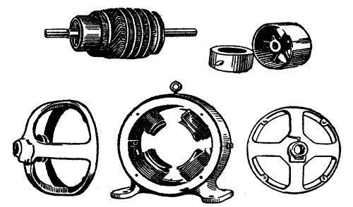 Armature and field coils of a direct current dynamo
One hundred lamps would provide 100 paths of 220 ohms resistance each to carry current, and the amount required to light 100 such lamps would be 100 × ˝ or 50 amperes. Every electrical device—a lamp,[Pg 108] a stove, an iron, a motor, etc.,—must, by regulations of the Fire Underwriters' Board be plainly marked with the voltage of the current for which it is designed and the amount of current it will consume. This is usually done by indicating its capacity in watts, which as we have seen, means volts times amperes, and from this one can figure ohms, by the above formulas.
A Short Circuit
We said a few paragraphs back that under no conditions must two bare wires leading from electric mains be permitted to touch each other, without some form of resistance being interposed in the form of lamps, or other devices. Let us see what would happen if two such bare wires did touch each other. Our dynamo as we discover by reading its plate, is rated to deliver 50 amperes, let us say, at 110 volts pressure. Modern dynamos are rated liberally, and can stand 100% overload for short periods of time, without dangerous overheating. Let us say that the[Pg 109] mains conveying current from the armature to the switchboard are five feet long, and of No. 2 B. & S. gauge copper wire, a size which will carry 50 amperes without heating appreciably. The resistance of this 10 feet of No. 2 copper wire, is, as we find by consulting a wire table, .001560 ohms. If we touch the ends of these two five-foot wires together, we instantly open a clear path for the flow of electric current, limited only by the carrying capacity of the wire and the back pressure of .001560 ohms resistance. Using Ohm's Law, C equals E divided by R, we find that C (amperes) equals 110/.001560 or 70,515 amperes!
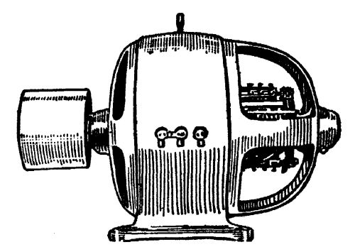 A direct current dynamo
Unless this dynamo were properly protected, the effect of such a catastrophe would be immediate and probably irreparable. In effect, it would be suddenly exerting a force of nearly 10,000 horsepower against the little 10 horsepower water wheel that is driving this[Pg 110] dynamo. The mildest thing that could happen would be to melt the feed-wire or to snap the driving belt, in which latter case the dynamo would come to a stop. If by any chance the little water wheel was given a chance to maintain itself against the blow for an instant, the dynamo, rated at 50 amperes, would do its best to deliver the 70,515 amperes you called for—and the result would be a puff of smoke, and a ruined dynamo. This is called a "short circuit"—one of the first "don'ts" in handling electricity.
As a matter of fact every dynamo is protected against such a calamity by means of safety devices, which will be described in a later chapter—because no matter how careful a person may be, a partial short circuit is apt to occur. Happily, guarding against its disastrous effects is one of the simplest problems in connection with the electric plant.
Direct Current and Alternating Current
When one has mastered the simple Ohm's Law of the electric circuit, the next step is to[Pg 111] determine what type of electrical generator is best suited to the requirements of a farm plant.
In the first place, electric current is divided into two classes of interest here—alternating, and direct.
We have seen that when a wire is moved through the field of a magnet, there is induced in it two pulsations—first in one direction, then in another. This is an alternating current, so called because it changes its direction. If, with our armature containing hundreds of wires to "cut" the lines of force of a group of magnets, we connected the beginning of each wire with one copper ring, and the end of each wire with another copper ring, we would have what is called an alternating-current dynamo. Simply by pressing a strap of flexible copper against each revolving copper ring, we would gather the sum of the current of these conductors. Its course would be represented by the curved line in the diagram, one loop on each side of the middle line (which represents time) would be a cycle. The number [Pg 112]of cycles to the second depends on the speed of the armature; in ordinary practice it is usually twenty-five or sixty. Alternating current has many advantages, which however, do not concern us here. Except under very rare conditions, a farmer installing his own plant should not use this type of machine.
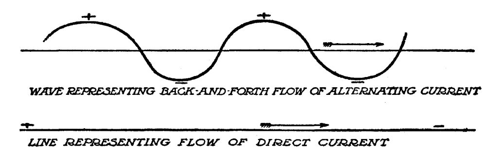 Diagram of alternating and direct current
If, however, instead of gathering all the current with brushes bearing on two copper rings, we collected all the current traveling in one direction, on one set of brushes—and all the current traveling in the other direction on another set of brushes,—we would straighten out this current, make it all travel in one direction. Then we would have a direct current. A direct current dynamo, the type generally used in private plants, does[Pg 113] this. Instead of having two copper rings for collecting the current, it has a single ring, made up of segments of copper bound together, but insulated from each other, one segment for each set of conductors on the armature. This ring of many segments, is called a commutator, because it commutates, or changes, the direction of the electric impulses, and delivers them all in one direction. In effect, it is like the connecting rod of a steam engine that straightens out the back-and-forth motion of the piston in the steam cylinder and delivers the motion to a wheel running in one direction.
Such a current, flowing through a coil of wire would make a magnet, one end of which would always be the north end, and the other end the south end. An alternating current, on the other hand, flowing through a coil of wire, would make a magnet that changed its poles with each half-cycle. It would no sooner begin to pull another magnet to it, than it would change about and push the other magnet away from it, and so on, as long as it continued to flow. This[Pg 114] is one reason why a direct current dynamo is used for small plants. Alternating current will light the same lamps and heat the same irons as a direct current; but for electric power it requires a different type of motor.
Types of Direct Current Dynamos
Just as electrical generators are divided into two classes, alternating and direct, so direct current machines are divided into three classes, according to the manner in which their output, in amperes and volts, is regulated. They differ as to the manner in which their field magnets (in whose field of force the armature spins) are excited, or made magnetic. They are called series, shunt, and compound machines.
The Series Dynamo
By referring to the diagram, it will be seen that the current of a series dynamo issues from the armature mains, and passes through the coils of the field magnets before passing into the external circuit to do its work. The[Pg 115] residual magnetism, or the magnetism left in the iron cores of the field magnets from its last charge, provides the initial excitation, when the machine is started. As the resistance of the external circuit is lowered, by turning on more and more lights, more and more current flows from the armature, through the field magnets. Each time the resistance is lowered, therefore, the current passing through the field magnets becomes more dense in amperes, and makes the field magnets correspondingly stronger.
We have seen that the voltage depends on the number of lines of magnetic force cut by the armature conductors in a given time. If the speed remains constant then, and the magnets grow stronger and stronger, the voltage will rise in a straight line. When no current is drawn, it is 0; at full load, it may be 100 volts, or 500, or 1,000 according to the machine. This type of machine is used only in street lighting, in cities, with the lights connected in "series," or one after another on the same wire, the last lamp finally returning[Pg 116] the wire to the machine to complete the circuit. This type of dynamo has gained the name for itself of "mankiller," as its voltage becomes enormous at full load. It is unsuitable, in every respect, for the farm plant. Its field coils consist of a few turns of very heavy wire, enough to carry all the current of the external circuit, without heating.
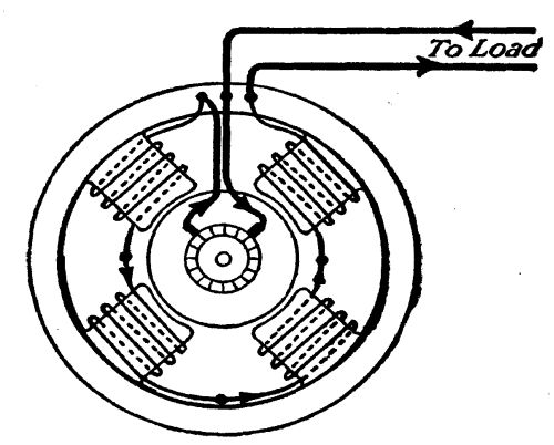 Connections of a series dynamo
The Shunt Dynamo
The shunt dynamo, on the other hand, has field coils connected directly across the circuit, from one wire to another, instead of in "series." These coils consist of a great many turns of very fine wire, thus introducing resistance into the circuit, which limits the amount of current (amperes) that can be forced through them at any given voltage. As a shunt dynamo is brought up to its rated speed, its voltage gradually rises until a condition [Pg 117]of balance occurs between the field coils and the armature. There it remains constant. When resistance on the external circuit is lowered, by means of turning on lamps or other devices, the current from the armature increases in working power, by increasing its amperes. Its voltage remains stationary; and, since the resistance of its field coils never changes, the magnets do not vary in strength.
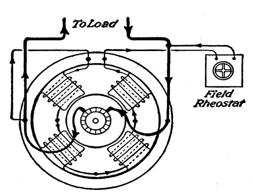 Connections of a shunt dynamo
The objection to this type of machine for a farm plant is that, in practice, the armature begins to exercise a de-magnetizing effect on the field magnets after a certain point is reached—weakens them; consequently the voltage begins to fall. The voltage of a shunt dynamo begins to fall after half-load is reached; and at full load, it has fallen possibly 20 per cent. A rheostat, or resistance[Pg 118] box on the switchboard, makes it possible to cut out or switch in additional resistance in the field coils, thus varying the strength of the field coils, within a limit of say 15 per cent, to keep the voltage constant. This, however, requires a constant attendance on the machine. If the voltage were set right for 10 lights, the lights would grow dim when 50 lights were turned on; and if it were adjusted for 50 lights, the voltage would be too high for only ten lights—would cause them to "burn out."
Shunt dynamos are used for charging storage batteries, and are satisfactory for direct service only when an attendant is constantly at hand to regulate them.
The Compound Dynamo
The ideal between these two conditions would be a compromise, which included the characteristics of both series and shunt effects. That is exactly what the compound dynamo effects.
A compound dynamo is a shunt dynamo[Pg 119] with just enough series turns on its field coils, to counteract the de-magnetizing effect of the armature at full load. A machine can be designed to make the voltage rise gradually, or swiftly, by combining the two systems. For country homes, the best combination is a machine that will keep the voltage constant from no load to full load. A so-called flat-compounded machine does this. In actual practice, this voltage rises slightly at the half-load line—only two or three volts, which will not damage the lamps in a 110-volt circuit.
The compound dynamo is therefore self-regulating, and requires no attention, except as to lubrication, and the incidental care given to any piece of machinery. Any shunt dynamo can be made into a compound dynamo, by winding a few turns of heavy insulated wire around the shunt coils, and connecting them in "series" with the external circuit. How many turns are necessary depends on conditions. Three or four turns to each coil usually are sufficient for "flat compounding." If the generating plant is a long[Pg 120] distance from the farm house where the light, heat, and power are to be used, the voltage drops at full load, due to resistance of the transmission wires. To overcome this, enough turns can be wound on top of the shunt coils to cause the voltage to rise at the switchboard, but remain stationary at the spot where the current is used. The usual so-called flat-compounded dynamo, turned out by manufacturers, provides for constant voltage at the switchboard. Such a dynamo is eminently fitted for the farm electric plant. Any other type of machine is bound to cause constant trouble and annoyance.
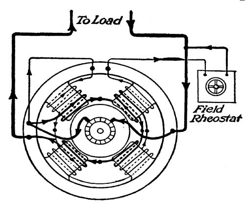 Connections of a compound dynamo
WHAT SIZE PLANT TO INSTALL
The farmer's wife his partner—Little and big plants—Limiting factors—Fluctuations in water supply—The average plant—The actual plant—Amount of current required for various operations—Standard voltage—A specimen allowance for electric light—Heating and cooking by electricity—Electric power: the electric motor.
The farmer's wife becomes his partner when he has concluded the preliminary measurements and surveys for building his water-power electric plant. Now the question is, how big a plant is necessary, or how small a plant can he get along with. Electricity may be used for a multitude of purposes on the farm, in its sphere of furnishing portable light, heat and power; but when this multitude of uses has been enumerated, it will be found that the wife shares in the benefits no less than the farmer himself. The greatest dividend of all,[Pg 122] whether dividends are counted in dollars or happiness, is that electricity takes the drudgery out of housework. Here, the work of the farmer himself ends when he has brought electricity to the house, just as his share in housework ends when he has brought in the kerosene, and filled the woodbox. Of the light and heat, she will use the lion's share; and for the power, she will discover heretofore undreamed-of uses. So she must be a full partner when it comes to deciding how much electricity they need.
How much electricity, in terms of light, heat, and power, will the farmer and his wife have use for? How big a plant should be installed to meet the needs of keeping house and running the farm?
The answer hangs mainly on how much water-power there is available, through all the seasons of the year, with which to generate electricity. Beyond that, it is merely a question of the farmer's pocketbook. How much money does he care to spend? Electricity is a cumulative "poison." The more one uses[Pg 123] it, the more he wants to use it. After a plant has been in operation a year, the family have discovered uses for electricity which they did not think of in the beginning. For this reason, it is well to put in a plant larger than the needs of the moment seem to require. An electrical horsepower or two one way or another will not greatly change the first cost, and you will always find use for any excess.
Once for all, to settle the question of water-power, the water wheel should be twice the normal capacity of the dynamo it drives, in terms of power. This allows for overload, which is bound to occur occasionally; and it also insures smooth running, easy governing, and the highest efficiency. Since the electric current, once the plant is installed, will cost practically nothing, the farmer can afford to ignore the power going to waste, and consider only how to get the best service.
The Two Extremes
The amount of water to be had to be turned into electricity, will vary with location, and[Pg 124] with the season. It may be only enough, the greater part of the year, for a "toy" plant—a very practical toy, by the way—one that will keep half a dozen lights burning in the house and barn at one time; under some conditions water may be so scarce that it must be stored for three or four days to get enough power to charge a storage battery for these six or eight lights. A one-quarter, or a one-half kilowatt electrical generator, with a one horsepower (or smaller) wheel, will light a farmstead very satisfactorily—much better than kerosene lamps.
On the other hand, the driving power of your wheel may be sufficient to furnish 50 or 100 lights for the house, barn, and out-buildings, and barn-yard and drives; to provide ample current for irons, toasters, vacuum cleaners, electric fans, etc.; to do all the cooking and baking and keep the kitchen boiler hot; and to heat the house in the coldest weather with a dry clean heat that does not vitiate the air, with no ashes, smoke or dust or woodchopping—nothing but an electric switch[Pg 125] to turn on and off; and to provide power for motors ranging from tiny ones to run the sewing machine, to one of 15 horsepower to do the threshing. A plant capable of developing from 30 to 50 kilowatts of electricity, and requiring from 50 to 100 horsepower at the water wheel, would do all this, depending on the size of the farmstead. One hundred horsepower is a very small water project, in a commercial way; and there are thousands of farms possessing streams of this capacity.
Fluctuations in Water Supply
It would be only during the winter months that such a plant would be driven to its full capacity; and since water is normally plentiful during these months, the problem of power would be greatly simplified. The heaviest draft on such a plant in summer would be during harvesting; otherwise it would be confined to light, small power for routine work, and cooking. Thus, a plant capable of meeting all the ordinary requirements of the four dry months of summer, when water is apt to[Pg 126] be scarce, doubles or quadruples its capacity during the winter months, to meet the necessities of heat for the house.
A dynamo requires only as much power to drive it, at any given time, as is being used in terms of electricity. There is some small loss through friction, of course, but aside from this the power required of the prime mover (the water wheel) is always in proportion to the amount of current flowing. When water is scarce, and the demands for current for heating are low, it is good practice to close a portion of the buckets of the turbine wheel with wooden blocks provided for this purpose. It is necessary to keep the speed of the dynamo uniform under all water conditions; and where there is a great fluctuation between high and low water periods, it is frequently necessary to have a separate set of pulleys for full gate and for half-gate. The head must remain the same, under all conditions. Changing the gate is in effect choking or opening the nozzle supplying the wheel, to cut down or increase its consumption of water.
The Average Plant
It will be the exceptional plant, however, among the hundreds of thousands to be had on our farms, which will banish not only the oil lamp and kitchen stove, but all coal or wood burning stoves as well—which will heat the house in below-zero weather, and provide power for the heavier operations of the farm. Also, on the other hand, it will be the exceptional plant whose capacity is limited to furnishing a half-dozen lights and no more.
A happy medium between these two conditions is the plant large enough to supply between five and ten electrical horsepower, in all seasons. Such a plant will meet the needs of the average farm, outside of winter heating and large power operations, and will provide an excess on which to draw in emergencies, or to pass round to one's neighbors. It is such a plant that we refer to when we say that (not counting labor) its cost, under ordinary conditions should not greatly exceed the price of one sound young horse for farm work.
Since the plant we described briefly in the first chapter, meets the requirements of this "average plant" let us inquire a little more fully into its installation, maintenance, and cost.
An Actual Plant
In this instance, the water-power was already installed, running to waste, in fact. The wheel consists of the so-called thirty-six inch vertical turbine, using 185 square inches of water, under a 14-foot head. Water is supplied to this wheel by a wooden penstock 33 inches square, inside measurements, and sloping at an angle of 30° from the flume to the wheel.
This wheel, under a 14-foot head, takes 2,312 cubic feet of water a minute; and it develops 46.98 actual horsepower (as may be figured by using the formulas of Chapter III). The water supply is provided by a small mountain river. The dam is 10 feet high, and the race, which feeds the flume from the mill pond is 75 yards long. The race has two spillways, one near the dam, and the second at the flume itself, to maintain an even head of water at all times.
Half-Gate
Since the water supply varies with the seasons, it has been found practical to run the wheel at half-gate—that is, with the gate only half-open. A set of bevel gears work the main shaft, which runs at approximately 200 revolutions per minute; and the dynamo is worked up to its required speed of 1,500 revolutions per minute through a countershaft.
The dynamo is a modern four-pole machine, compound-wound, with a rated output of 46 amperes, at 125 volts—in other words a dynamo of 5.75 kilowatts capacity, or 7.7 electrical horsepower. At full load this dynamo would require a driving power of 10 horsepower, counting it as 75 per cent efficient; and, to conform to our rule of two water horsepower to one electrical horsepower, the wheel should be capable of developing 20 horsepower. As a matter of fact, in this[Pg 130] particular instance, shutting down the wheel to half-gate more than halves the rated power of the wheel, and little more than 15 horsepower is available. This allowance has proved ample, under all conditions met with, in this plant.
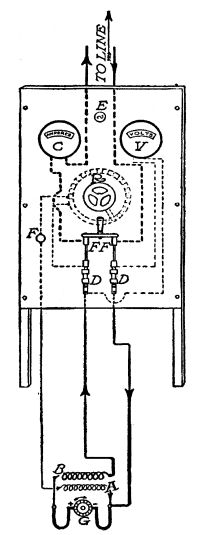 A switchboard and its connections: G. Dynamo; A.
Shunt field coils; B. Series coils; DD. Fuses; FF. Main switch;
F. Field switch; C. Ammeter; V. Voltmeter; E. Lamp; R.
Rheostat. Dotted lines show connections on back of board
A switchboard and its connections: G. Dynamo; A.
Shunt field coils; B. Series coils; DD. Fuses; FF. Main switch;
F. Field switch; C. Ammeter; V. Voltmeter; E. Lamp; R.
Rheostat. Dotted lines show connections on back of board
The dynamo is mounted on a firm floor foundation; and it is belted from the countershaft by an endless belt running diagonally. A horizontal belt drive is the best. Vertical drive should be avoided wherever possible.
The Switchboard
The switchboard originally consisted of a wooden frame on which were screwed ordinary asbestos shingles, and the instruments were mounted on these. Later, a sheet of electric insulating fibre was substituted, for look's sake. The main requisite is something substantial—and fireproof. The switchboard instruments consist of a voltmeter, with a range of from 0 to 150 volts; an ammeter, with a range, 0 to 75 amperes; a field regulating rheostat (which came with the dynamo); a main switch, with[Pg 131] cartridge fuses protecting the machine against a draft of current over 60 amperes; and two line switches for the two owners, one fuse at 20 amperes, and the other at 40 amperes. Electric fuses are either cartridges or plugs, enclosing lead wire of a size corresponding to their rating. All the current of the line they protect passes through this lead wire. If the current drawn exceeds the capacity of the lead wire, it melts from the heat, and thus opens the circuit, and cuts off the current.
Items of Cost
This water wheel would cost $250 new. There is a duplicate in the neighborhood bought at second-hand, for $125. The[Pg 132] dynamo cost $90, and was picked up second-hand in New York City. New it would cost $150. The voltmeter cost $7, and the ammeter $10; and the switches and fuses could be had for $5. A wheel one-half the size, using one-half the amount of water at full gate, would do the work required, and the cost would be correspondingly less.
Capacity
This plant supplies two farms with electric light. One farm (that of the owner of the wheel) has 30 lamps, of 16 candlepower each, and two barn-yard lamps of 92 candlepower each. His wife has an electric iron and an electric water heater. Needless to say, all these lamps, and the iron and water heater are not in use at one time.
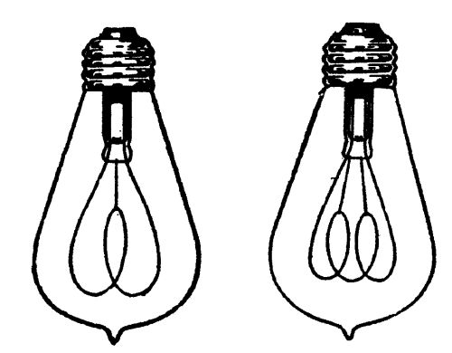 Carbon Lamps Gem Type (Ľ scale)
The partner who owns the electric part of the plant has 30 lamps in his house and barn,[Pg 133] many of them being 25 watt tungsten, which give more light for less power, but cost more to buy. They are not all in use at one time, though (since the current costs nothing) the inclination is to turn them on at night and let them burn. In his kitchen he has an electric range, and a water heater for the 40 gallon boiler. In addition to this he has all sorts of appliances,—irons, toasters, grills, a vacuum cleaner, a vibrator, etc. Naturally all these appliances are not in use at one time, else the draft on the plant would be such as to "blow" the fuses. For instance, all the baking is done in daylight; and when the oven is used after dark, they are careful to turn off all lights not needed. An ideal plant, of course, would be a plant big enough to take care of the sum of lamps and handy devices used at one time.
To make this plant ideal, (for, being an actual affair, it has developed some short-comings, with the extension of the use of electricity) it would require a dynamo whose capacity can be figured, from the following:
| Watts | |
| 15 carbon lamps, 16 candlepower, @60 watts each | 900 |
| 10 tungsten lamps, 20 candlepower, @25 watts each | 250 |
| 2 tungsten lamps, 92 candlepower, @100 watts each | 200 |
| Water heater, continuous service | 800 |
| Toaster, occasional service | 600 |
| Iron, occasional service | 400 |
| Oven-baking, roasting, etc | 2,000 |
| 2 stove plates @1,000 watts each | 2,000 |
| 1 stove plate | 400 |
| Vacuum cleaner, occasional service | 200 |
| Vibrator, occasional service | 100 |
| Small water heater, quart capacity | 400 |
| Small motor, Ľ horsepower, occasional | 250 |
| Motor, ˝ hp, pumping water, etc | 500 |
| Electric fan, occasional service | 100 |
| ——— | |
| Total current, one house | 9,100 |
| 30 carbon lamps, 16 candlepower, @60 | 1,800 |
| 2 lamps, 100 watt tungsten | 200 |
| Electric iron | 400 |
| Small water or milk heater | 600 |
| ——— | |
| Total current, 2nd house | 3,000 |
| 1st house | 9,100 |
| ——— | |
| 12,100 |
Thus, in this plant, if every electrical device were turned on at once, the demand on the dynamo would be for 12.1 kilowatts, or an overload of over 100 per cent. The main-switch fuse, being for 60 amperes, would "blow" or melt, and cut off all current for the[Pg 135] moment. To repair the damage would be merely the work of a second—and at a cost of a few cents—simply insert a new fuse, of which there must be a supply on hand at all times. Or, if either owner exceeded his capacity, the line fuses (one for 20 amperes, and the other for 40 amperes) would instantly cut off all current from the greedy one.
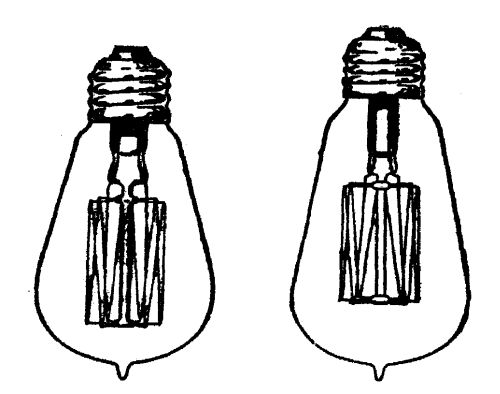 25 and 40 watt Mazda tungsten lamps (Ľ scale)
Lessons From This Plant
The story of this plant illustrates two things which the farmer and his wife must take into account when they are figuring how much electricity they require. First, it illustrates how one uses more and more current, as he finds it so serviceable and labor-saving, and at the same time free. The electric range and the water boiler, in the above instance, were later acquisitions not counted on in figuring the original installation. Second, it illustrates,[Pg 136] that while the normal load of this generator is 5.75 kilowatts, one does not have to limit the electrical conveniences in the home to this amount. True, he cannot use more electricity than his plant will produce at any one time,—but it is only by a stretch of the imagination that one may conceive the necessity of using them all at once. Ironing, baking, and the use of small power are usually limited to daylight hours when no lights are burning.
As a matter of fact, this plant has proved satisfactory in every way; and only on one or two occasions have fuses been "blown", and then it was due to carelessness. A modern dynamo is rated liberally. It will stand an overload of as much as 100 per cent for a short time—half an hour or so. The danger from overloading is from heating. When the machine grows too hot for the hand, it is beginning to char its insulation, to continue which, of course would ruin it. The best plant is that which works under one-half or three-quarters load, under normal demands.
Standard Voltage
We are assuming the farmer's plant to be, in 99 cases out of 100, the standard 110-volt, direct current type. Such a plant allows for at least a 10 per cent regulation, in voltage, up or down the scale; supplies for this voltage are to be had without delay in even the more remote parts of the country, and (being sold in greater volume) they are cheaper than those for other voltages.
There are two general exceptions to this rule as to 110-volt plants: (1) If the plant is located at a distance greater than a quarter of a mile from the house, it will be found cheaper (in cost of transmission line, as will be shown later) to adopt the 220-volt plant; (2), If the water supply is so meagre that it must be stored for many hours at a time, and then used for charging storage batteries, it will be found most economical to use a 30-volt plant. A storage battery is made up of cells of approximately 2 volts each; and, since more than 55 such cells would be required for a[Pg 138] 110-volt installation, its cost would be prohibitive, with many farmers.
So we will assume that this plant is a 110-volt plant, to be run without storage battery. It will be well to make a chart, dividing the farm requirements into three heads—light, heat, and power.
Light
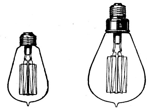 60 and 100 watt Mazda tungsten lamp. These lamps may be
had in sizes from 10 to 500 watts (Ľ scale)
60 and 100 watt Mazda tungsten lamp. These lamps may be
had in sizes from 10 to 500 watts (Ľ scale)
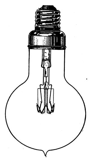 The lamp of the future. A 1000 watt Mazda nitrogen
lamp, giving 2000 candlepower (Ľ scale)
The lamp of the future. A 1000 watt Mazda nitrogen
lamp, giving 2000 candlepower (Ľ scale)
Light is obtained by means of incandescent lamps. There are two styles in common use, the carbon and the tungsten lamp. It requires 3.5 to 4 watts of electricity to produce one candlepower in a carbon lamp. It requires[Pg 139] from 1 to 1.25 watt to produce one candlepower in the tungsten lamp. The new nitrogen lamp, not yet in general use, requires only ˝ watt to the candlepower. Since tungsten lamps give three times the light of the carbon lamp, they are the most economical to use in the city or town where one is paying for commercial current. But, in the country where water-power furnishes current for nothing, it will be found most economical to use the carbon lamp, since its cost at retail is 16 cents, as compared with 30 cents for a corresponding size in tungsten. A 60 watt carbon lamp, of 16 candlepower; or a 25 watt tungsten lamp, of 20[Pg 140] candlepower, are the sizes to use. In hanging lamps, as over the dining room table, a 100 watt tungsten lamp, costing 70 cents, and giving 92 candlepower light is very desirable; and for lighting the barn-yard, these 100 watt tungsten lamps should be used. For reading lamps, the tungsten style, of 40 or 60 watt capacity, will be found best. Otherwise, in all locations use the cheaper carbon lamp. Both styles have a rated life of 1,000 hours, after which they begin to fall off in efficiency. Here again, the farmer need not worry over lack of highest efficiency, as a lamp giving only 80 per cent of its rated candlepower is still serviceable when he is not paying for the current. With care not to use them at voltages beyond their ratings, lamps will last for years.
A Specimen Light Allowance
Below is a typical table of lights for a large farm house, the barns and barn-yard. It is given merely as a guide, to be varied for each individual case:
| Watts | |
| Kitchen, 2 lights @60 watts | 120 |
| Dining room, 1 light, tungsten | 100 |
| Living room, table lamp with 3 tungstens @40 | 120 |
| Living room, 2 wall fixtures, 4 lamps @60 watts | 240 |
| Parlor, same as living room | 360 |
| Pantry, 1 hanging lamp | 60 |
| Cellar, one portable lamp | 60 |
| Woodshed, 1 hanging lamp | 60 |
| 2 bedrooms, 2 lights each @ 60 | 240 |
| 2 bed rooms, 1 light each @60 | 120 |
| Bathroom, 1 "turn-down" light, @60 | 60 |
| Hall, downstairs, 2 lights @60 | 120 |
| Hall, upstairs, 1 light | 60 |
| Attic, 1 light | 60 |
| Porch, 1 light | 60 |
| Barn and barn-yard: | |
| Barn-yard entrance, 1 tungsten | 100 |
| Watering trough, 1 tungsten | 100 |
| Front gate, 1 tungsten | 100 |
| Horse barn, 4 lights @60 | 240 |
| Cow barn, 4 lights @60 | 240 |
| Pig house, 1 light | 60 |
| Hay barn, 2 lights, @60 | 120 |
| ——— | |
| Total for farmstead | 2,800 |
This provides for 44 lights, an extremely liberal allowance. How many of these lights will be burning at any one time? Probably not one-half of them; yet the ideal plant is that which permits all fixtures to be in service at one time on the rare occasions when necessary. Thus, for lighting only, 2,800[Pg 142] watts maximum service would require a 4 kilowatt generator, and 10 water horsepower, on the liberal rating of two to one. A 3 kilowatt generator would take care of these lights, with a 30 per cent overload (which is not excessive) for maximum service. The above liberal allowance of lights may be cut in two, or four—or even eight—and still throw a kerosene lamp in shadow. It all depends on the number of lights one wants burning at one time; and the power of the water wheel.
If the 36 carbon lights in the above table were replaced by 25 watt tungsten lights, the saving in power would be 35 watts each, or 1,260 watts, nearly two electrical horsepower; while the added first cost would be 14 cents a light, or $5.04. A generator of 2 kilowatt capacity would take care of all these lights then, with 460 watts to spare.
Heating
Electric heating and cooking is in its infancy, due to the prohibitive cost of commercial [Pg 143]current in our cities. Here the farmer has the advantage again, with his cheap current.
For heating the house, it is calculated that 2 watts is required for each cubic foot of air space in a room, during ordinary winter weather. Thus, a room 10 × 12, and 8 feet high, would contain 960 cubic feet, and would require 1,820 watts energy to heat it in cold weather. Five such rooms would require 9.1 kilowatts; and 10 such rooms, or their equivalent, would require 18.2 kilowatts.
Electric heating devices are divided into two classes: (1) those which can be used on lamp circuits, and do not draw more than 660 watts each; and (2) those which draw more than 660, therefore require special wiring. The capacity of these devices is approximately as follows:
Lamp circuit devices:
| Watts | |
| Electric iron | 400 to 660 |
| Toaster | 350 to 660 |
| Vacuum cleaner | 200 to 400 |
| Grill | 400 to 660 |
| Small water heater | 400 to 660 |
| Hot plates | 400 to 660 |
Lamp circuit devices:
| Coffee percolator | 400 to 660 |
| Chafing dish | 400 to 660 |
| Electric fan | 100 to 250 |
Special circuit devices:
| Hot water boiler heater | 800 to 1,200 |
| Small ovens | 660 to 1,200 |
| Range ovens | 1,200 to 3,000 |
| Range, hot plates | 400 to 1,300 |
| Radiators (small) | 750 to 1,500 |
| Radiators (large) | 1,500 to 6,000 |
The only device in the above list which is connected continuously, is the hot water boiler, and this can be credited with at least one electrical horsepower 24 hours a day. It is a small contrivance, not much bigger than a quart can, attached to the back of the kitchen boiler, and it keeps the water hot throughout the house at all hours. Its cost will vary with the make, ranging from $8 to $15; and since it is one of the real blessings of the farm kitchen and bathroom, it should be included in all installations where power permits. Electric radiators will be used 24 hours a day in winter, and not at all in summer. They are portable, and can[Pg 145] be moved from room to room, and only such rooms as are in actual use need be heated. The other devices are for intermittent service, many of them (like the iron) for only a few hours each week.
The grill, chafing dish, coffee percolator, etc., which are used on the dining room table while the family is at meals, each draw an equivalent of from 6 to 10 carbon lights. By keeping this in view and turning off spare lights, one can have the use of them, with even a small plant. Thus, a one kilowatt plant permits the use of any one of these lamp circuit devices at a time, with a few lights in addition.
Power
Electric power is to be had through motors. A direct current dynamo and a direct current motor are identical in construction. That is, a motor becomes a generator if belted to power; and a generator becomes a motor, if connected to electric mains. This is best illustrated by citing the instance of a trans-continental[Pg 146] railroad which crosses the Bitter Root Mountains by means of electric power. Running 200 miles up a 2 per cent grade, it is drawn[Pg 147] by its motors. Coasting 200 miles down the 2 per cent grade on the other side of the mountains, its motors become generators. They act as brakes, and at the same time they pump the power of the coasting weight of this train back into the wires to help a train coming up the other side of the mountains.
 Connections of shunt motor and starting rheostat
Just as there are three types of direct current generators, so there are three types of direct current motors: series, shunt, and compound, with features already explained in the case of generators. Motors are rated by horsepower, and generators are rated by kilowatts. Thus a one kilowatt generator has a capacity of 1,000 watts; as a motor, it would be rated as 1000/746 horsepower, or 1.34 horsepower. Their efficiency varies with their size, ranging from 40 to 60 per cent in very small motors, and up to 95 per cent in very large ones. The following table may be taken as a guide in calculating the power required by motors, on 110-volt circuits:
| Ľ Horsepower | 2˝ amperes, or 275 watts |
| ˝ hp | 4˝ amperes, or 500 watts |
| 1 hp | 9 amperes, or 990 watts |
| 2 hp | 17 amperes, or 1.97 kilowatts |
| 3 hp | 26 amperes, or 2.86 kilowatts |
| 5 hp | 40 amperes, or 4.40 kilowatts |
| 7˝ hp | 60 amperes, or 6.60 kilowatts |
| 10 hp | 76 amperes, or 8.36 kilowatts |
| 15 hp | 112 amperes, or 12.32 kilowatts |
An electric motor, in operation, actually generates electricity, which it pushes back into the line as a counter-electromotive-force. The strength of this counter force, in volts, depends on the motor's speed, the same as if it were running as a dynamo. For this reason, when a motor is started, and before it comes up to speed, there would be a rush of current from the line, with nothing to hold it back, and the motor would be burned out unless some means were provided to protect it for the moment. This is done by means of a starting rheostat, similar to the regulating rheostat on the dynamo switchboard. This resistance box is connected in "series" with the armature, in the case of shunt and compound motors; and with the entire[Pg 149] motor circuit in the case of a series machine.
A series motor has a powerful starting torque, and adjusts its speed to the load. It is used almost altogether in street cars. It can be used in stump pulling, or derrick work, such as using a hay fork. It must always be operated under load, otherwise, it would increase in speed until it tore itself to pieces through mechanical strain. The ingenious farmer who puts together an electric plow, with the mains following behind on a reel, will use a series motor.
A shunt motor should be used in all situations where a fairly uniform speed under load is required, such as separating, in milking machines, running a lathe, an ensilage cutter, vacuum cleaners, grinders, etc.
The compound motor has the characteristics of the series and shunt motors, giving an increased starting torque, and a more nearly constant speed under varying loads than the shunt motor, since the latter drops off slightly in speed with increasing load.
Flexible Power
An electric motor is an extremely satisfactory form of power because it is so flexible. Thus, one may use a five horsepower motor for a one horsepower task, and the motor will use only one electrical horsepower in current—just enough to overcome the task imposed on it. For this reason, a large-sized motor may be used for any operation, from one requiring small power, up to its full capacity. It will take an overload, the same as a dynamo. In other words it is "eager" for any task imposed on it; therefore it must be protected by fuses, or it will consume itself, if too big an overload is imposed on it.
A one horsepower shunt or compound motor is very serviceable for routine farm operations, such as operating the separator, the churn, the milking machine, grinder, pump, and other small power jobs. Motors of Ľ horsepower are handy in the kitchen, for grinding knives, polishing silver, etc., and can be used also for vacuum cleaners, and running the sewing[Pg 151] machine. For the larger operations, motors will vary from three horsepower for cutting ensilage, to fifteen horsepower for threshing. They can be mounted on trucks and conveyed from one point to another, being fed current from the mains by means of suitable wires wound on reels.
Remember, in estimating the size of your plant for light, heat, and power, that it does not have to be big enough to use all the devices at one time. Also remember, that two water horsepower to one electrical horsepower is a very liberal allowance; and that a generator working under one-half or two-thirds capacity at normal loads will require less attention than a machine constantly being worked above its capacity. Therefore, let your generator be of liberal size, because the difference in cost between a 5 and 10 kilowatt machine is not in proportion to their capacity. In fact (especially among second-hand machines), the difference in cost is very small. The mere fact that the generator is of 110 electrical horsepower capacity does not require[Pg 152] a turbine of 20 horsepower. The chances are that (unless you wish to heat your house and do large power jobs) you will not use more than 3 to 5 electrical horsepower normally; therefore an allowance of 10 water horsepower, in this case, would be ample. A plant used simply for lighting the house and barn, for irons, and toasters, and one horsepower motors, need not exceed 2 or 2˝ kilowatts for the generator, and 5 or 6 horsepower for the turbine wheel. Normally it would not use one-half this capacity.
TRANSMISSION LINES
Copper wire—Setting of poles—Loss of power in transmission—Ohm's Law and examples of how it is used in figuring size of wire—Copper-wire tables—Examples of transmission lines—When to use high voltages—Over-compounding a dynamo to overcome transmission loss.
Having determined on the location of the farm water-power electric plant, and its capacity, in terms of electricity, there remains the wiring, for the transmission line, and the house and barn.
For transmission lines, copper wire covered with waterproof braid—the so-called weatherproof wire of the trade—is used. Under no circumstances should a wire smaller than No. 8, B. & S. gauge be used for this purpose, as it would not be strong enough mechanically. The poles should be of chestnut or cedar, 25 feet long, and set four feet in the ground. Where it is necessary to follow highways, they[Pg 154] should be set on the fence line; and in crossing public highways, the ordinance of your own town must guide you. Some towns prescribe a height of 19 feet above the road, others 27 feet, some 30. Direct current, such as is advised for farm installations, under ordinary circumstances, does not affect telephone wires, and therefore transmission lines may be strung on telephone poles. Poles are set at an average distance of 8 rods; they are set inclined outward on corners. Sometimes it is necessary to brace them with guy wires or wooden braces. Glass insulators are used to fasten the wires to the cross-arms of the poles, and the tie-wires used for this purpose must be the same size as the main wire and carry the same insulation.
Size of Wire for Transmission
To determine the size of the transmission wires will require knowledge of the strength of current (in amperes) to be carried, and the distance in feet. In transmission, the electric current is again analogous to water flowing in[Pg 155] pipes. It is subject to resistance, which cuts down the amount of current (in watts) delivered.
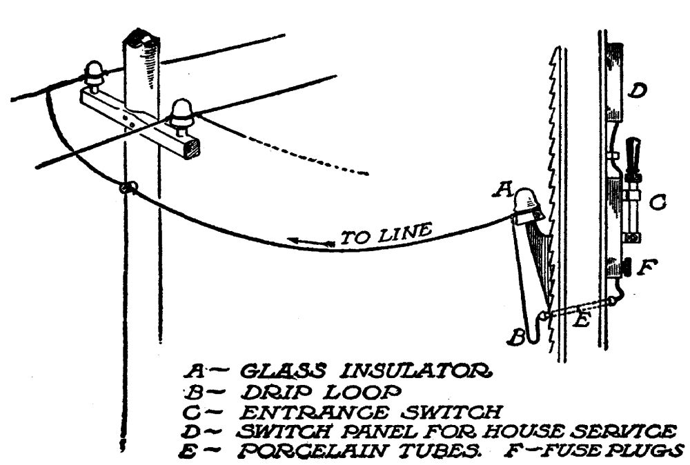 Bringing wires into the house or barn
The loss in transmission is primarily measured in volts; and since the capacity of an electric current for work equals the volts multiplied by amperes, which gives watts, every volt lost reduces the working capacity of the current by so much. This loss is referred to by electrical engineers as the "C^2R loss," which is another way of saying that the loss is equal to the square of the current in amperes, multiplied by ohms resistance. Thus, if the[Pg 156] amperes carried is 10, and the ohms resistance of the line is 5, then the loss in watts to convey that current would be (10 × 10) × 5, or 500 watts, nearly a horsepower.
The pressure of one volt (as we have seen in another chapter) is sufficient to force one ampere, through a resistance of one ohm. Such a current would have no capacity for work, since its pressure would be consumed in the mere act of transmission.
If, however, the pressure were 110 volts, and the current one ampere, and the resistance one ohm, the effective pressure after transmission would be 110-1, or 109 volts.
To force a 110-volt current of 50 amperes through the resistance of one ohm, would require the expenditure of 50 volts pressure. Its capacity for work, after transmission, would be 110-50, or 60 volts, × 50 amperes, or 3,000 watts. As this current consisted of 110 × 50, or 5,500 watts at the point of starting, the loss would be 2,500 watts, or about 45 per cent. It is bad engineering to allow more than 10 per cent loss in transmission.
There are two ways of keeping this loss down. One is by increasing the size of the transmission wires, thus cutting down the resistance in ohms; the other way is by raising the voltage, thus cutting down the per cent loss. For instance, suppose the pressure was 1,100 volts, instead of 110 volts. Five amperes at 1,100 volts pressure, gives the same number of watts, power, as 50 amperes, at 110 volts pressure. Therefore it would be necessary to carry only 5 amperes, at this rate. The loss would be 5 volts, or less than ˝ of 1 per cent, as compared with 45 per cent with 110 volts.
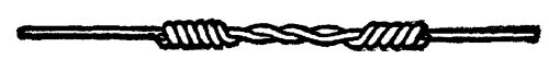 Splicing transmission wire
In large generating stations, where individual dynamos frequently generate as much as 20,000 horsepower, and the current must be transmitted over several hundred miles of territory, the voltage is frequently as high as 150,000, with the amperes reduced in proportion. Then the voltage is lowered to a suitable rate, and the amperage raised in proportion, by special machinery, at the point of use.
It is the principle of the C^2R loss, which the[Pg 158] farmer must apply in determining the size of wire he is to use in transmitting his current from the generator switchboard to his house or barn. The wire table on page 159, together with the formula to be used in connection with it, reduce the calculations necessary to simple arithmetic. In this table the resistance of the various sizes of wire is computed from the fact that a wire of pure copper 1 foot long, and 1/1000 inch in diameter (equal to one circular mill) offers a resistance of 10.6 ohms to the foot. The principle of the C^2R loss is founded on Ohm's Law, which is explained in Chapter V.
The formula by which the size of transmission wire is determined, for any given distance, and a given number of amperes, is as follows:

In other words, multiply the distance in feet from mill to house by 22, and multiply this product by the number of amperes to be[Pg 159] carried. Then divide the product by the number of volts to be lost; and the result will be the diameter of the wire required in circular mills. By referring to the table above, the B. & S. gauge of the wire necessary for transmission, can be found from the nearest corresponding number under the second column, entitled "circular mills area."
COPPER WIRE TABLE
| B.& S. Gauge | Feet per Lb. | Area in circular mills | (R) Ohms per 1,000 feet | Feet per Ohm | (R) Ohms per pound |
| 0000 | 1.561 | 211,600.0 | .04904 | 20,392.90 | .00007653 |
| 000 | 1.969 | 167,805.0 | .06184 | 16,172.10 | .00012169 |
| 00 | 2.482 | 133,079.0 | .07797 | 12,825.40 | .00019438 |
| 0 | 3.130 | 105,534.0 | .09829 | 10,176.40 | .00030734 |
| 1 | 3.947 | 83,694.0 | .12398 | 8,066.00 | .00048920 |
| 2 | 4.977 | 66,373.0 | .15633 | 6,396.70 | .00077784 |
| 3 | 6.276 | 52,634.0 | .19714 | 5,072.50 | .00123700 |
| 4 | 7.914 | 41,742.0 | .24858 | 4,022.90 | .00196660 |
| 5 | 9.980 | 33,102.0 | .31346 | 3,190.20 | .00312730 |
| 6 | 12.58 | 26,250.0 | .39528 | 2,529.90 | .00497280 |
| 7 | 15.87 | 20,816.0 | .49845 | 2,006.20 | .00790780 |
| 8 | 20.01 | 16,509.0 | .62840 | 1,591.10 | .01257190 |
| 9 | 25.23 | 13,094.0 | .79242 | 1,262.00 | .01998530 |
| 10 | 31.82 | 10,381.0 | .99948 | 1,000.50 | .03178460 |
| 11 | 40.12 | 8,234.0 | 1.26020 | 793.56 | .05054130 |
| 12 | 50.59 | 6,529.9 | 1.58900 | 629.32 | .08036410 |
| 13 | 63.79 | 5,178.4 | 2.00370 | 499.06 | .12778800 |
| 14 | 80.44 | 4,106.8 | 2.52660 | 395.79 | .20318000 |
| 15 | 101.4 | 3,256.7 | 3.18600 | 313.87 | .32307900 |
| 16 | 127.9 | 2,582.9 | 4.01760 | 248.90 | .51373700 |
| 17 | 161.3 | 2,048.2 | 5.06600 | 197.39 | .81683900 |
| 18 | 203.4 | 1,624.3 | 6.38800 | 156.54 | 1.29876400 |
CARRYING CAPACITY OF WIRES AND WEIGHT
| B. & S. Gauge No. | Weight 1,000 ft. Weatherproof (Pounds) | Carrying capacity Weatherproof (Amperes) | Carrying capacity rubber cov. (Amperes) |
| 0000 | 800 | 312 | 175 |
| 000 | 666 | 262 | 145 |
| 00 | 500 | 220 | 120 |
| 0 | 363 | 185 | 100 |
| 1 | 313 | 156 | 95 |
| 2 | 250 | 131 | 70 |
| 3 | 200 | 110 | 60 |
| 4 | 144 | 92 | 50 |
| 5 | 125 | 77 | 45 |
| 6 | 105 | 65 | 35 |
| 7 | 87 | 55 | 30 |
| 8 | 69 | 46 | 25 |
| 10 | 50 | 32 | 20 |
| 12 | 31 | 23 | 15 |
| 14 | 22 | 16 | 10 |
| 16 | 14 | 8 | 5 |
| 18 | 11 | 5 | 3 |
Since two wires are required for electrical transmission, the above formula is made simple by counting the distance only one way, in feet, and doubling the resistance constant, 10.6, which, for convenience is taken as 22, instead of 21.2.
Examples of Transmission Lines
As an example, let us say that Farmer Jones has installed a water-power electric plant on his brook, 200 yards distant from his house. The generator is a 5 kilowatt machine, capable of producing 45 amperes at 110 volts pressure. He has a 3 horsepower motor, drawing 26 amperes at full load; he has 20 lights of varying capacities, requiring[Pg 161] 1,200 watts, or 10 amperes when all on; and his wife uses irons, toasters, etc., which amount to another 9 or 10 amperes—say 45 altogether. The chances are that he will never use all of the apparatus at one time; but for flexibility, and his own satisfaction in not having to stop to think if he is overloading his wires, he would like to be able to draw the full 45 amperes if he wishes to. He is willing to allow 5 per cent loss in transmission. What size wires will be necessary, and what will they cost? Substituting these values in the above formula, the result is:

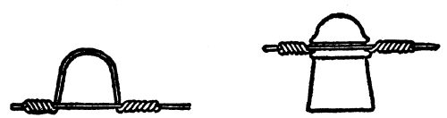 Transmission wire on glass insulator
Referring to the table, No. 0 wire is 105,534 circular mills, and is near enough; so this wire would be used. It would require 1,200 feet,[Pg 162] which would weigh, by the second table, 435.6 pounds. At 19 cents a pound, it would cost $82.76.
Farmer Jones says this is more money than he cares to spend for transmission. As a matter of fact, he says, he never uses his motor except in the daytime, when his lights are not burning; so the maximum load on his line at any one time would be 26 amperes, not 45. What size wire would he use in this instance?
Substituting 26 for 45 in the equation, the result is 61,300 circular mills, which corresponds to No. 2 wire. It would cost $57.00.
Now, if Farmer Jones, in an emergency, wished to use his motor at the same time he was using all his lights and his wife was ironing and making toast—in other words, if he wanted to use the 45 amperes capacity of his dynamo, how many volts would he lose? To get this answer, we change the formula about, until it reads as follows:

Substituting values, we have, in this case,
nearly, less than 10 per cent. This is a very efficient line, under the circumstances. Now if he is willing to lose 10 per cent on half-load, instead of full load, he can save still more money in line wire. In that case (as you can find by applying the formula again), he could use No. 5 wire, at a cost of $28.50. He would lose 11 volts pressure drawing 26 amperes; and he would lose 18 volts pressure drawing 45 amperes, if by any chance he wished to use full load.
In actual practice, this dynamo would be regulated, by means of the field resistance, to register 110 plus 11 volts, or 121 volts at the switchboard to make up for the loss at half-load. At full load, his voltage at the end of the line would be 121 minus 18, or 103 volts; his motor would run a shade slower, at this voltage, and his lights would be slightly dimmer. He would probably not notice the difference. If he did, he could walk over to his generating station, and raise[Pg 164] the voltage a further 7 volts by turning the rheostat handle another notch.
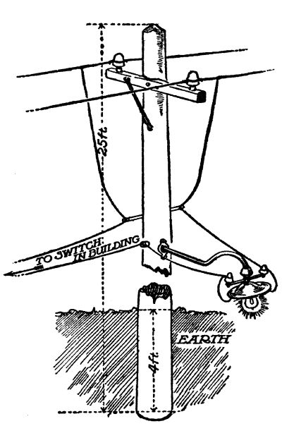 A barn-yard light
Thousands of plants can be located within 100 feet of the house. If Farmer Jones could do this, he could use No. 8 wire, costing $2.62. The drop in pressure would be 5.99 volts at full load—so small it could be ignored entirely. In this case the voltmeter should be made to read 116 volts at the switchboard, by means of the rheostat.
If, on the other hand, this plant were 1,000 feet away from the house and the loss 10 volts the size wire would be
a No. 0 wire comes nearest to this figure, and its cost, for 2,000 feet, at 19 cents a pound, would be $137.94.[Pg 165] A No. 0000 wire, costing $294.00, would give a 5 per cent drop at full load. In this case, the cost of transmission can be reduced to a much lower figure, by allowing a bigger drop at half-load, with regulation at the switchboard. Thus, a No. 2 wire here, costing but $95, would be satisfactory in every way. The loss at half-load would be about 9 volts, and the rheostat would be set permanently for 119 or 120 volts. A modern dynamo can be regulated in voltage by over 25 per cent in either direction, without harm, if care is taken not to overload it.
Benefit of Higher Voltages
If Farmer Jones' plant is a half of a mile away from the house, he faces a more serious proposition in the way of transmission. Say he wishes to transmit 26 amperes with a loss of 10 volts. What size wire will be necessary?

A No. 000 wire is nearest this size, and 5,280 feet of it would cost over $650.00. This cost[Pg 166] would be prohibitive. If, however, he installed a 220-volt dynamo—at no increase in cost—then he would have to transmit only a half of 26 amperes, or 13 amperes, and he could allow 22 volts loss, counting 10 per cent. In this case, the problem would work out as follows:
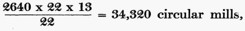
or approximately a No. 5 wire which, at 19 cents a pound, would cost $120.65.
Install a 550-volt generator, instead of a 220-volt machine and the amperes necessary would be cut to 5.2, and the volts lost would be raised to 55. In this case a No. 12 wire would carry the current; but since it would not be strong enough for stringing on poles, a No. 8 wire would be used, costing about $63.
It will be readily seen from these examples how voltage influences the efficiency of transmission. Current generated at a pressure in excess of 550 volts is not to be recommended for farm plants unless an expert is in charge.[Pg 167] A safer rule is not to exceed 220 volts, for while 550 volts is not necessarily deadly, it is dangerous. When one goes into higher voltages, it is necessary to change the type of dynamo to alternating current, so that the current can be transformed to safe voltages at the point where it is used. Since only the occasional farm plant requires a high-tension system, the details of such a plant will not be gone into here.
In transmitting the electric current over miles of territory, engineers are accustomed to figure 1,000 volts for each mile. Since this is a deadly pressure, it should not be handled by any one not an expert, which, in this case, the farmer is not.
Over-Compounding the Generator
One can absorb the loss in transmission frequently, by over-compounding the machine. In describing the compound machine, in Chapter Five, it is shown that the usual compound dynamo on the market is the so-called flat-compounded type. In such a dynamo, the[Pg 168] voltage remains constant at the switchboard, from no load to full load, allowing for a slight curve which need not be taken into account.
Now, by adding a few more turns to the series wires on the field coils of such a dynamo, a machine is to be had which gradually raises its voltage as the load comes on in increasing volume. Thus, one could secure such a machine, which would begin generating at 110 volts, and would gradually rise to 150 at full load. Yet the voltage would remain constant at the point of use, the excess being absorbed in transmission. A machine of this type can be made to respond to any required rise in voltage.
As an example of how to take advantage of this very valuable fact, let us take an instance:
Say that Farmer Jones has a transmission line 1,000 feet long strung with No. 7 copper wire. This 2,000 feet of wire would introduce a resistance of one ohm in the circuit. That is, every ampere of current drawn at his house would cause the working voltage there to fall[Pg 169] one volt. If he drew 26 amperes, the voltage would fall, at the house, 26 volts. If his switchboard voltage was set at say 120, the voltage at his house, at 26 amperes of load, would fall to 94 volts, which would cause his lights to dim considerably. It would be a very unsatisfactory transmission line, with a flat-compounded dynamo.
On the other hand, if his dynamo was over-compounded 25 per cent—that is, if it gained 28 volts from no load to full load, the system would be perfect. In this case, the dynamo would be operated at 110 volts pressure at the switchboard with no load. At full load the voltmeter would indicate 110 plus 26, or 136 volts. The one or two lights burned at the power plant would be subject to a severe strain; but the 50 or 100 lights burned at the house and barn would burn at constant voltage, which is very economical for lamps.
The task of over-compounding a dynamo can be done by any trained electrician. The farmer himself, if he progresses far enough in his study of electricity, can do it. It is necessary [Pg 170]to remove the top or "series" winding from the field coils. Count the number of turns of this wire to each spool. Then procure some identical wire in town and begin experimenting. Say you found four turns of field wire to each spool. Now wind on five, or six, being careful to wind it in the same direction as the coils you removed and connect it in the same way. If this additional number of turns does not raise the voltage enough, in actual practice, when the dynamo is running from no load to full load, add another turn or two. With patience, the task can be done by any careful mechanic. The danger is in not winding the coils the same way as before, and getting the connections wrong. To prevent this mistake, make a chart of the "series" coils as you take them off.
To make the task of over-compounding your own dynamo even more simple, write to the manufacturers, giving style and factory number of your machine. Tell them how much voltage rise you wish to secure, and ask them how many turns of "series" wire should[Pg 171] be wound on each spool in place of the old "series" coil. They could tell you exactly, since they have mathematical diagrams of each machine they make.
Avoid overloading an over-compounded machine. Since its voltage is raised automatically, its output in watts is increased a similar amount at the switchboard, and, for a given resistance, its output in amperes would be increased the same amount, as can be ascertained by applying Ohm's Law. Your ammeter is the best guide. Your machine is built to stand a certain number of amperes, and this should not be exceeded in general practice.
WIRING THE HOUSE
The insurance code—Different kinds of wiring described—Wooden moulding cheap and effective—The distributing panel—Branch circuits—Protecting the circuits—The use of porcelain tubes and other insulating devices—Putting up chandeliers and wall brackets—"Multiple" connections—How to connect a wall switch—Special wiring required for heat and power circuits—Knob and cleat wiring, its advantages and drawbacks.
The task of wiring your house is a simple one, with well-defined rules prescribed by your insurance company. Electricity, properly installed, is much safer than oil lamps—so much so indeed that insurance companies are ready to quote especial rates. But they require that the wiring be done in accordance with rules laid down by their experts, who form a powerful organization known as the National Board of Fire Underwriters. Ask your insurance agent for a copy of the code rules.
Danger of fire from an electric current comes from the "short circuit," partial or complete; and it is against this danger that the rules guard one. The amount of electricity flowing through a short circuit is limited only by the fuse protecting that line; and since there is no substance known that can withstand the heat of the electric arc, short circuits must be guarded against. Happily the current is so easily controlled that the fire hazard is eliminated entirely—something which cannot be done with oil lamps.
In house-wiring for farm plants, the wire should be rubber-covered, and not smaller than No. 14 B. & S. gauge. This is the wire to use on all lamp circuits. It costs about $0.85 cents per 100 feet. There are four kinds of wiring permitted, under the insurance code:
(1) Flexible armoured cable: This consists of two-wire cable, protected with a covering of flexible steel. It is installed out of sight between the walls, and provides suitable outlets for lamps, etc., by means of metal boxes[Pg 174] set flush with the plaster. It is easily installed in a house being built, but requires much tearing down of plaster for an old house. Since its expense prohibits it in the average farm house, this system will not be described in detail here.
(2) Rigid and flexible conduit: As the name implies this system consists of iron pipe, in connection with flexible conduit, run between the walls. It differs from the above system, in that the pipes with their fittings and outlet boxes are installed first, and the wires are then "fished" through them. Duplex wires—the two wires of the circuit woven in one braid—are used; and a liberal amount of soapstone, and occasionally kerosene, are used to make the wires slip easily into place. This is the most expensive system, and the best; but it is difficult to install it in an old house without tearing down a good deal of plaster. It has the advantage of being absolutely waterproof and fireproof.
(3) Wooden moulding: This is simply moulding, providing two raceways for the insulated wires to run in, and covered with a capping. It is nailed or screwed firmly to the wall, on top of the plaster; and when the wires have been installed in their respective slots and the capping tacked on, the moulding is given a coat of paint to make it in harmony with the other moulding in the room. This system is cheap, safe, and easily installed, and will be described in detail here.
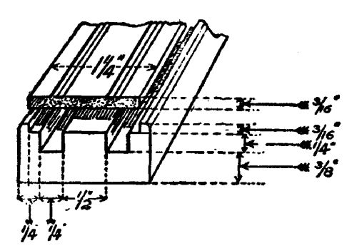 Detail of wooden moulding
(4) Open wiring: In open wiring, the wires are stretched from one support to another (such as beams) and held by means of porcelain cleats, or knobs. It is the simplest to install; but it has the objection of leaving the wires unprotected, and is ugly. It is very satisfactory in barns or out-buildings however.
The Distributing Panel
The first point to consider in wiring a house with wooden moulding is the distribution board. It should be located centrally, on the wall near the ceiling, so as to be out of ordinary reach. It consists of a panel of wood—though fireproof material is better—firmly screwed to the wall, and containing in a row, the porcelain cut-outs, as shown in the cut, from which the various branch circuits are to be led. Each cut-out provides for two branch circuits; and each branch contains receptacles for two plug fuses. These fuses should be of 6 amperes each. The Insurance Code limits the amount of electricity that may be drawn on any branch lamp circuit to 660 watts; and these fuses protect the circuit from drafts beyond this amount.
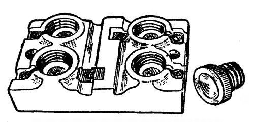 Porcelain cut-out and plug fuse
The mains, leading from the entrance switch, as shown in the diagram, to the panel[Pg 177] board, should be of the same size as the transmission wire itself, and rubber-covered. These mains terminate at the distributing board. They are connected to the terminals of the cut-outs by means of heavy brass screws.
Wire Joints
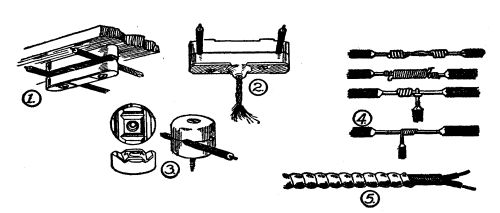 Examples of cleat and knob wiring, 1, 2, 3; wire
joints, 4; flexible armoured conductor, 5
Examples of cleat and knob wiring, 1, 2, 3; wire
joints, 4; flexible armoured conductor, 5
The branch circuits are, as has been said, of No. 14 rubber-covered wire, running concealed in wooden moulding. All joints or splices in this wire are made, as shown in the illustration, by first scraping the wires bright, and fastening them stoutly together. This joint is then soldered, to make the connection electrically perfect. Soft solder is used, with[Pg 178] ordinary soldering salts. There are several compounds on the market, consisting of soft solder in powder form, ready-mixed with flux. Coat the wire joint with this paste and apply the flame of an alcohol lamp. The soldered joint is then covered with rubber tape, and over this ordinary friction tape is wound on. A neat joint should not be larger than the diameter of the wire before insulation is removed.
Branch Circuits
First, make a diagram of your rooms and indicate where you wish lamps, or outlets for other purposes. Since wooden moulding can be run across ceilings, and up or down walls, lamps may be located in places where they are out of the way. In planning the circuit, remember that you will want many outlets in handy places on the walls, from which portable cords will convey current to table lamps, to electric irons and toasters and other handy devices which can be used on the lamp circuit. These outlets are made of porcelain,[Pg 179] in two pieces. One piece is merely a continuation of the moulding itself; and the other is a cap to connect permanently to the end of the lamp or iron cord, which may be snapped into place in a second. Since there are a great many designs of separable current taps on the market, it is well to select one design and stick to it throughout the house, so that any device can be connected to any outlet.
The code permits 660 watts on each circuit. This would allow 12 lamps of 55 watts each. It is well to limit any one circuit to 6 lamps; this will give leeway for the use of small stoves, irons, toasters, etc. without overloading the circuit and causing a fuse to blow.
Having installed your distributing board, with its cut-outs, figure out the course of your first branch circuit. Let us say it will provide lights and outlets for the dining room and living room. It will be necessary to run the wires through the partitions or floors in several places. For this purpose porcelain tubes should be used, costing one to three cents each. Knock holes in the plaster at the determined[Pg 180] point, insert the tubes so they project ľ inch on each side, and fill up the ragged edge of the hole neatly with plaster.
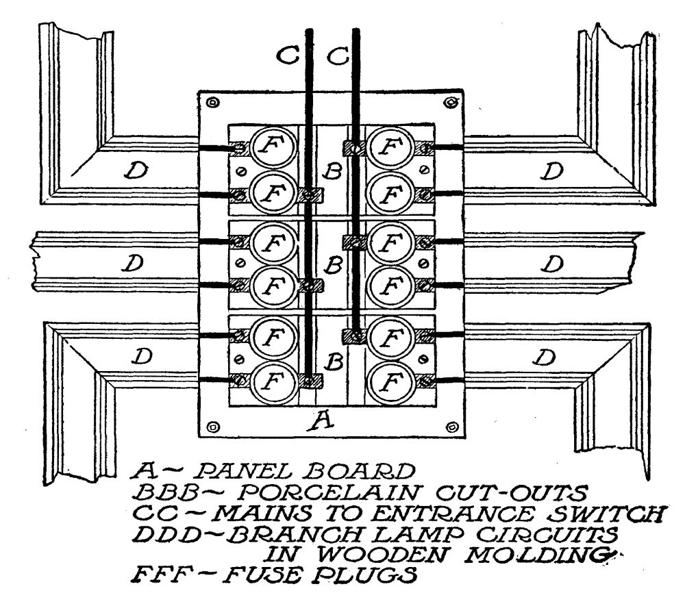 The distributing panel
When all the tubes have been set in place, begin laying the moulding. Run it in a straight line, on the wall against the ceiling wherever possible, mitering the joints neatly. Whenever it is necessary to change the run from the ceiling to the wall and a miter cannot be made, the wires should be protected in[Pg 181] passing from one slot to the other by being enclosed in non-metallic flexible conduit, called circular loom.
In running wooden moulding, avoid brick walls liable to sweat or draw dampness; keep away from places where the heat of a stove might destroy the rubber insulation of the wires; do not pass nearer than six inches to water pipes when possible—and when it is necessary to pass nearer than this, the wooden moulding should pass above the pipe, not below it, with at least an inch of air space intervening, thus avoiding dampness from sweating of pipes.
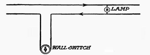 Snap switch connections
Places where chandeliers or wall bracket lamps are to be installed permanently are fitted with wooden terminal blocks, which fit[Pg 182] over the moulding and flush with the plaster. These, after holes have been bored in them for the wires, and the wires drawn through, should be screwed firmly to the wall or ceiling, always choosing a joist or beam for support. Then a crow's-foot, or tripod of iron, tapped and threaded for iron pipe, is screwed to the terminal block. The iron pipe of the chandelier or wall bracket is then screwed home in this crow's-foot.
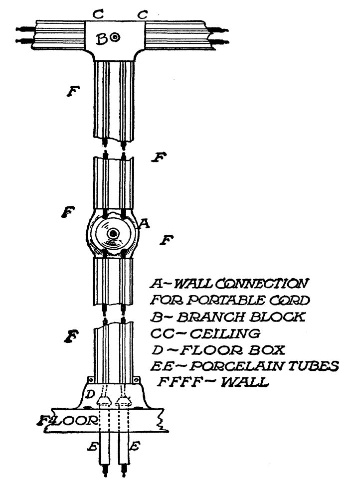 Detail of wooden moulding
Do not begin stringing wires until all the moulding of the circuit has been laid. Then thread the wires through the wall or floor tubes and lay them in their respective slots. If trouble be found making them stay in place before the capping is put on, small tacks may be driven into the moulding beside them to hold them. When a terminal block is reached, a loop is made of each wire, through the hole cut in the block, if the circuit is to continue in the same direction. If it is to end there, the two wires are drawn through taut, and cut off at a length of 5 or 6 inches. These end wires, or loops, are then scraped bare and[Pg 183] spliced to the two wires coming out of the chandelier or wall bracket. This joint is then soldered and covered with tape, and the shell of the chandelier is screwed into place, covering the joint.
If the moulding is run along the walls flush with the ceiling, as is usual, a branch is made for a wall light, or wall tap, by means of a porcelain "T," or branch-block, which provides the means for running the circuit at right angles to itself without letting the wires come in contact with each other where they cross. Separable current taps should be installed in handy places on all circuits, so that small heating devices may be used without removing the lamps from their sockets. The two wires are bared for half an inch where they run through these current taps, and are fastened by means of brass screws.
"Multiple" Connections
All electric devices for this installation—lamps, irons, vacuum cleaners, motors—must be connected across the circuit—that is, bridged, from one wire to the other. This is called multiple, or shunt connection. There is only one exception to it, in wiring the house. That one exception is installing a wall switch, the ordinary snap switch. Since this wall[Pg 185] switch, is, in effect, merely an instrument, which opens or closes a circuit, it should be connected to only one wire, which is cut to provide two ends for the screw connections in the switch. When a moulding branch is run down from the ceiling to some convenient spot for a snap switch (with which to turn the lights of a room on or off), a porcelain "T" is not used. All that is necessary to do is to loop the bottom wire of the circuit down through the branch moulding, and connect it to the switch at a terminal block, or porcelain base.
In wiring lamp fixtures, No. 14 rubber-covered wire will usually prove too large. For this purpose, No. 18 may be used, with one lamp to each loop. Hanging lamps may not be supported by electric lamp cord itself, if there is more than one lamp in the cluster, because the weight is apt to break the electrical connections. In such a case, the lamp should be supported by a chain, and the twisted cord conveying current to the electric bulbs, is woven in the links of the chain. For the pantry, kitchen, woodshed, barn, etc., a[Pg 186] single hanging lamp may be suspended from a fielding rosette, as shown in the cut, provided a single knot is tied inside both the rosette and the lamp socket, to make it secure. This makes a very cheap fixture. The rosette of porcelain will cost 15 cents; the lamp socket 20 cents, and the lamp cord suspending the lamp and carrying the current will cost 1˝ cents a foot; while a tin shade will cost another 15 cents.
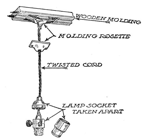 Detail of simple hanging lamp supported by rosette
Official Inspection
In all communities, your insurance agent must inspect and pass your wiring before you are permitted to throw the main switch and turn on the electricity. Frequently they require that the moulding be left uncapped, until they have inspected it. If you have more than 660 watts in lamps to a circuit; if your joints are not soldered and well taped; if the moulding is used in any concealed or damp place, the agent is liable to condemn your work and refuse permission to turn on the electricity. However the rules are so clearly defined that it is difficult to go wrong; and a farmer who does his own wiring and takes pride in its appearance is more apt to be right than a professional electrician who is careless at his task. After the work has been passed, tack on the moulding capping, with brads, and paint the moulding to match the woodwork.
Wooden moulding wiring is perfectly satisfactory if properly installed. It is forbidden[Pg 188] in many large cities, because of the liability of careless workmanship. It should never be installed in damp places, or out of sight. If the work is well done, the system leaves nothing to be desired; and it has the additional advantage of being cheap, and easily done by any farmer who can use carpenter tools. Farmers with moulding machinery can make their own moulding. The code prescribes it shall be of straight-grained wood; that the raceways for the wires shall be separated by a tongue of wood one-half inch wide; and that the backing shall be at least 3/8 inch thick. It must be covered, inside and out, with at least two coats of moisture-repellant paint. It can be had ready-made for about 2 cents a foot.
Special Heating Circuits
If one plans using electricity for heavy-duty stoves, such as ranges and radiators, it is necessary to install a separate heating circuit. This is the best procedure in any event, even when the devices are all small and suited to[Pg 189] lamp circuits. The wire used can be determined by referring to the table for carrying capacity, under the column headed "rubber-covered." A stove or range drawing 40 amperes, would require a No. 4 wire, in moulding. A good plan is to run the heating circuit through the basement, attaching it to the rafters by means of porcelain knobs. Branches can then be run up through the floor to places where outlets are desired. Such a branch circuit should carry fuses suitable to the allowed carrying capacity of the wire.
Knob and Cleat Wiring
Knob and cleat wiring, such as is used extensively for barns and out-buildings, requires little explanation. The wires should not be closer than 2˝ inches in open places, and a wider space is better. The wires should be drawn taut, and supported by cleats or knobs at least every four feet. In case of branch circuits, one wire must be protected from the other it passes by means of a porcelain tube. It should never be used in damp[Pg 190] places, and should be kept clear of dust and litter, and protected from abrasion.
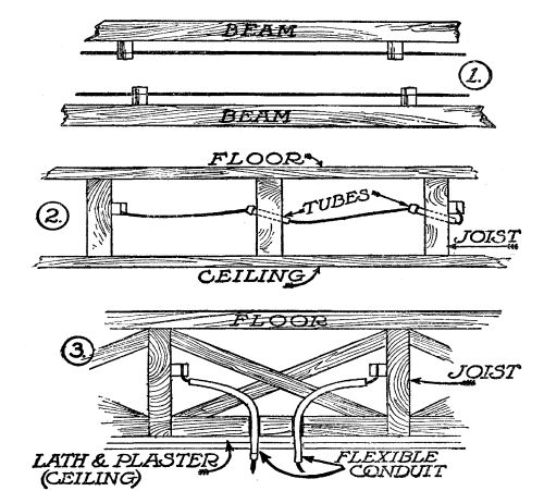 Knob and cleat wiring
Knob and tube wiring is frequently used in houses, being concealed between walls or flooring. In this case, the separate wires are stretched on adjoining beams or rafters, and porcelain tubes are used, in passing through cross beams. For a ceiling or wall outlet, a spliced branch is passed through the plaster by means of porcelain tubes or flexible loom.[Pg 191]
Wires from the house to the barn should be uniform with transmission wires. At the point of entry to buildings they must be at least six inches apart, and must take the form of the "drop loop" as shown in the illustration. A double-pole entrance switch must be provided, opening downward, with a double-pole fuse. In passing over buildings wires must not come closer than 7 feet to flat roofs, or one foot to a ridge roof. Feed-wires for electric motors should be determined from the table of safe carrying capacities, and should be of liberal size.
THE ELECTRIC PLANT AT WORK
Direct-connected generating sets—Belt drive—The switchboard—Governors and voltage regulators—Methods of achieving constant pressure at all loads: Over-compounding the dynamo; A system of resistances; (A home-made electric radiator); Regulating voltage by means of the rheostat—Automatic devices—Putting the plant in operation.
Dynamos may be connected to water wheels either by means of a belt, or the armature may spin on the same shaft as the water wheel itself. The latter is by far the more desirable way, as it eliminates the loss of power through shafting and belting, and does away altogether with the belts themselves as a source of trouble. An installation with the water wheel and armature on the same shaft is called a "direct-connected set" and is of almost universal use in large power plants.
To be able to use such a direct-connected[Pg 193] set, the dynamo must be designed to develop its full voltage when run at a speed identical with that of the water wheel. That is, if the dynamo is wound to be run at a speed of 800 revolutions per minute, it must be driven by a water wheel which runs at this speed and can be governed within narrow limits. Small impulse wheels running under great heads attain high speed, and for such wheels it is possible to obtain a suitable dynamo at low cost. For instance, a 12-inch impulse wheel, running under a 200-foot head will develop 6ľ horsepower when running at a speed of 875 revolutions per minute. A dynamo for direct coupling to such a wheel should have a rated speed within 5 per cent of 875 r.p.m.; and, as generators of this speed are to be had from the stock of almost all manufacturers, there would be no extra charge.
When it comes to the larger wheels, however, of the impulse type, or to turbines operating under their usual head the question becomes a little more difficult. In such cases, the speed of the water wheel will vary[Pg 194] from 150 revolutions per minute, to 400, which is slow speed for a small dynamo. As a general rule, the higher the speed of a dynamo, the lower the cost; because, to lower the speed for a given voltage, it is necessary either to increase the number of conductors on the armature, or to increase the number of field coils, or both. That means a larger machine, and a corresponding increase in cost.
In practice, in large plants, with alternating-current machines it has become usual to mount the field magnets on the shaft, and build the armature as a stationary ring in whose air space the field coils revolve. This simplifies the construction of slow-speed, large-output dynamos. Such a machine, however, is not to be had for the modest isolated plant of the farmer with his small water-power.
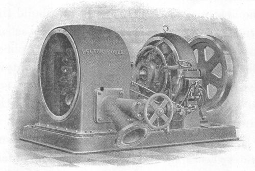 A tangential wheel, and a dynamo keyed to the same
shaft—the ideal method for generating electricity. The centrifugal
governor is included on the same base
A tangential wheel, and a dynamo keyed to the same
shaft—the ideal method for generating electricity. The centrifugal
governor is included on the same base
Dynamos can be designed for almost any waterwheel speed, and, among small manufacturers especially, there is a disposition to furnish these special machines at little advance in price over their stock machines. Frequently it is merely a matter of changing the winding on a stock machine. The farmer himself, in many cases, can re-wind an old dynamo to fit the speed requirements of a direct-connected drive if the difference is not too[Pg 195] great. All that would be necessary to effect this change would be to get the necessary winding data from the manufacturer himself, and proceed with the winding. This data would give the gauge of wire and the number of turns required for each spool of the field magnets; and the gauge of wire and number of turns required for each slot in the armature. The average boy who has studied electricity (and there is something about electricity that makes it closer to the boy's heart than his pet dog) could do this work. The advantages of direct drive are so many that it should be used wherever possible.
When direct drive cannot be had, a belt must be used, either from a main shaft, or a countershaft. The belt must be of liberal size, and must be of the "endless" variety—with a scarfed joint. Leather belt lacing, or even the better grades of wire lacing, unless [Pg 196]very carefully used, will prove unsatisfactory. The dynamo feels every variation in speed, and this is reflected in the lights. There is nothing quite so annoying as flickering lights. Usually this can be traced to the belt connections. Leather lacing forms a knot which causes the lights to flicker at each revolution of the belt. The endless belt does away with this trouble. Most dynamos are provided with sliding bases, by which the machine can be moved one way or another a few inches, to take up slack in the belt. To take advantage of this, the belt must be run in a horizontal line, or nearly so. Vertical belting is to be avoided.
The dynamo is mounted on a wooden base, in a dry location where it is protected from the weather, or dampness from any source. It must be mounted firmly, to prevent vibration when running up to speed; and the switchboard should occupy a place within easy reach. Wires running from the dynamo to the switchboard should be protected from injury, and must be of ample size to carry[Pg 197] the full current of the machine without heating. A neat way is to carry them down through the flooring through porcelain tubes, thence to a point where they can be brought up at the back of the switchboard. If there is any danger of injury to these mains they may be enclosed in iron pipe. Keep the wires out of sight as much as possible, and make all connections on the back of the switchboard.
The Switchboard
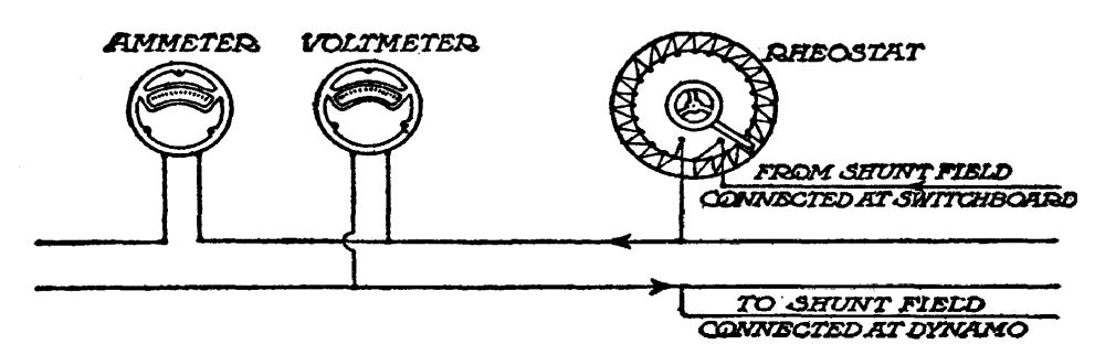 Connecting switchboard instruments
The switchboard is constructed of some fireproof material, preferably slate or marble. When the cost of this material is an item to consider, build a substantial wooden frame for your switchboard. You can then screw asbestos shingles to this to hold the various[Pg 198] instruments and with a little care such a switchboard can be made to look business-like, and it is fully as serviceable as the more expensive kind. The switchboard instruments have already been described briefly. They consist of a voltmeter (to measure voltage); an ammeter (to measure the strength of the current drawn, in amperes), a rheostat (to regulate the voltage of the machine to suit the individual requirements); and the usual switches and fuses. The main switch should be so wired that when open it will throw all the current off the line, but still leave the field coils, the voltmeter, and the switchboard lamp in circuit. The main-switch fuses should have a capacity about 50 per cent in excess of the full load of the dynamo. If the machine is rated for 50 amperes, 75-ampere fuses should be installed. This permits throwing on an overload in an emergency; and at the same time guards against a short circuit. If the capacity of the machine is under 30 amperes, plug fuses, costing 3 cents each, can be used. If it is[Pg 199] above this capacity, cartridge fuses, costing a little more, are required. A supply of these fuses should be kept handy at all times.
Governors and Voltage Regulators
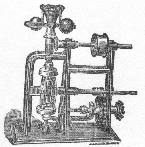 A centrifugal governor
The necessity for water wheel governors will vary with conditions. As a general rule, it may be said that reaction turbines working under a low head with a large quantity of water do not require as much governing as the impulse wheel, working under high heads with small quantities of water. When governing is necessary at all, it is because the prime mover varies in speed from no load to full load. Planning one's plant with a liberal allowance of power—two water horsepower to one electrical horsepower is liberal—reduces the necessity of governors to a[Pg 200] minimum. As an instance of this, the plant described in some detail in Chapters One and Six of this volume, runs without a governor.
However, a surplus of water-power is not usual. Generally plants are designed within narrow limits; and then the need of a governor becomes immediately apparent. There are many designs of governors on the market, the cheapest being of the centrifugal type, in which a pair of whirling balls are connected to the water wheel gate by means of gears, and open or close the gate as the speed lowers or rises.
Constant speed is necessary because voltage is directly dependent on speed. If the speed falls 25 per cent, the voltage falls likewise; and a plant with the voltage varying between such limits would be a constant source of annoyance, as well as expense for burned-out lamps.
Since constant voltage is the result aimed at by the use of a governor, the same result can be attained in other ways, several of which will be explained here briefly.
Over-Compounding
(1) Over-compounding the dynamo. This is simple and cheap, if one buys the right dynamo in the first instance; or if he can do the over-compounding himself, by the method described in the concluding paragraphs of Chapter Seven. If it is found that the speed of the water wheel drops 25 per cent between no load and full load, a dynamo with field coils over-compounded to this extent would give a fairly constant regulation. If you are buying a special dynamo for direct drive, your manufacturer can supply you with a machine that will maintain constant voltage under the normal variations in speed of your wheel.
A System of Resistances
(2) Constant load systems. This system provides that the dynamo shall be delivering a fixed amount of current at all times, under which circumstances the water wheel would not require regulation, as the demands on it would not vary from minute to minute or hour to hour.
This system is very simply arranged. It consists of having a set of "resistances" to throw into the circuit, in proportion to the amount of current used.
Let us say, as an example, that a 50-ampere generator is used at a pressure of 110 volts; and that it is desirable to work this plant at 80 per cent load, or 40 amperes current draft. When all the lights or appliances were in use, there would be no outside "resistance" in the circuit. When none of the lights or appliances were in use (as would be the case for many hours during the day) it would be necessary to consume this amount of current in some other way—to waste it. A resistance permitting 40 amperes of current to flow, would be necessary. Of what size should this resistance be?
The answer is had by applying Ohm's Law, explained in Chapter Five. The Law in this case, would be read R = E/C. Therefore, in this case R = 110/40 = 2ľ ohms resistance, would be required, switched across the mains, to keep the dynamo delivering its normal load.
The cheapest form of this resistance would[Pg 203] be iron wire. In place of iron wire, German silver wire could be used. German silver wire is to be had cheaply, and is manufactured in two grades, 18% and 30%, with a resistance respectively 18 and 30 times that of copper for the same gauge. Nichrome wire has a resistance 60 times that of copper; and manganin wire has a resistance 65 times that of copper, of the same gauge.
First figure the number of feet of copper wire suitable for the purpose. Allowing 500 circular mills for each ampere, the gauge of the wire should be 40 × 500 = 20,000 circular mills, or approximately No. 7 B. & S. gauge. How many feet of No. 7 copper wire would give a resistance of 2ľ ohms? Referring to the copper wire table, we find that it requires 2006.2 of No. 7 wire to make one ohm. Then 2ľ ohms would require 5,517 feet.
Since 30 per cent German silver wire is approximately 30 times the resistance of copper, a No. 7 German silver wire, for this purpose, would be 1/30 the length of the copper wire, or 186 feet. If nichrome wire[Pg 204] were used, it would be 1/60th the length of copper for the same gauge, or 93 feet. This resistance wire can be wound in spirals and made to occupy a very small space. As long as it is connected in circuit, the energy of the dynamo otherwise consumed as light would be wasted as heat. This heat could be utilized in the hot water boiler or stove when the lights were turned off.
In actual practice, however, the resistance necessary to keep the dynamo up to full load permanently, would not be furnished by one set of resistance coils. Each lamp circuit would have a set of resistance coils of its own. A double-throw switch would turn off the lamps and turn on the resistance coils, or vice versa.
Let us say a lamp circuit consisted of 6 carbon lamps, of 16 candlepower each. It would consume 6 × ˝ ampere, or 3 amperes of current, and interpose a resistance of 36.6 ohms—say 37 ohms. Three amperes would require a wire of at least 1,500 circular mills in area for safety. This corresponds to a No. 18[Pg 205] wire. A No. 18 copper wire interposes a resistance of one ohm, for each 156.5 feet length. For 37 ohms, 5,790 feet would be required, for copper wire, which of course would be impractical. Dividing by 30 gives 193 feet for 30% German silver wire; and dividing by 60 gives 96 feet of nichrome wire of the same gauge.
It is simple to figure each circuit in this way and to construct resistance units for each switch. Since the resistance units develop considerable heat, they must be enclosed and protected.
A Home-made Stove or Radiator
While we are on the subject of resistance coils it might be well here to describe how to make stoves for cooking, and radiators for heating the house, at small expense. These stoves consist merely of resistances which turn hot—a dull red—when the current is turned on. Iron wire, German silver wire, or the various trade brands of resistance wire, of which nichrome, calido, and manganin are samples,[Pg 206] can be used. In buying this wire, procure the table of resistance and carrying capacity from the manufacturers. From this table you can make your own radiators to keep the house warm in winter. Iron wire has the disadvantage of oxidizing when heated to redness, so that it goes to pieces after prolonged use. It is cheap, however, and much used for resistance in electrical work.
Let us say we wish to heat a bathroom, a room 6 × 8, and 8 feet high—that is a room containing 384 cubic feet of air space. Allowing 2 watts for each cubic foot, we would require 768 watts of current, or practically 7 amperes at 110 volts. What resistance would be required to limit the current to this amount? Apply Ohm's Law, as before, and we have R equals E divided by C, or R equals 110 divided by 7, which is 15.7 ohms. Forty-two feet of No. 20 German silver wire would emit this amount of heat and limit the current output to 7 amperes. In the Far West, it is quite common, in the outlying district, to find electric radiators made out of iron pipe covered[Pg 207] with asbestos, on which the requisite amount of iron wire is wound and made secure. This pipe is mounted in a metal frame. Or the frame may consist of two pipes containing heating elements; and a switch, in this case, is so arranged that either one or two heating elements may be used at one time, according to the weather. An ingenious mechanic can construct such a radiator, experimenting with the aid of an ammeter to ascertain the length of wire required for any given stove.
Regulating Voltage at Switchboards
The voltage of any given machine may be regulated, within wide limits, by means of the field rheostat on the switchboard.
A dynamo with a rated speed of 1,500 revolutions per minute, for 110 volts, will actually attain this voltage at as low as 1,200 r.p.m. if all the regulating resistance be cut out. You can test this fact with your own machine by cutting out the resistance from the shunt field entirely, and starting the[Pg 208] machine slowly, increasing its speed gradually, until the voltmeter needle registers 110 volts. Then measure the speed. It will be far below the rated speed of your machine.
If, on the other hand, the speed of such a machine runs up to 2,500 or over—that is, an excess of 67%—the voltage would rise proportionally, unless extra resistance was cut in. By cutting in such resistance—by the simple expedient of turning the rheostat handle on the switchboard,—the field coils are so weakened that the voltage is kept at the desired point in spite of the excessive speed of the machine. Excessive speeds are to be avoided, as a rule, because of mechanical strain. But within a wide range, the switchboard rheostat can be used for voltage regulation.
As it would be a source of continual annoyance to have to run to the switchboard every time the load of the machine was varied greatly this plan would not be practical for the isolated plant, unless the rheostat could be installed,—with a voltmeter—in one's[Pg 209] kitchen. This could be done simply by running a small third wire from the switchboard to the house. Then, when the lights became dim from excessive load, a turn of the handle would bring them back to the proper voltage; and when they flared up and burned too bright, a turn of the handle in the opposite direction would remedy matters. By this simple arrangement, any member of the family could attend to voltage regulation with a minimum of bother.
Automatic Devices
There are several automatic devices for voltage regulation at the switchboard on the market. These consist usually of vibrator magnets or solenoids, in which the strength of the current, varying with different speeds, reacts in such a way as to regulate field resistance. Such voltage regulators can be had for $40 or less, and are thoroughly reliable.
To sum up the discussion of governors and voltage regulators: If you can allow a liberal[Pg 210] proportion of water-power, and avoid crowding your dynamo, the chances are you will not need a governor for the ordinary reaction turbine wheel. Start your plant, and let it run for a few days or a few weeks without a governor, or regulator. Then if you find the operation is unsatisfactory, decide for yourself which of the above systems is best adapted for your conditions. Economy as well as convenience will affect your decision. The plant which is most nearly automatic is the best; but by taking a little trouble and giving extra attention, a great many dollars may be saved in extras.
Starting the Dynamo
You are now ready to put your plant in operation. Your dynamo has been mounted on a wooden foundation, and belted to the countershaft, by means of an endless belt.
See that the oil cups are filled. Then throw off the main switch and the field switch at the switchboard; open the water gate slowly,[Pg 211] and occasionally test the speed of the dynamo. When it comes up to rated speed, say 1,500 per minute, let it run for a few minutes, to be sure everything is all right.
Having assured yourself that the mechanical details are all right, now look at the voltmeter. It is probably indicating a few volts pressure, from 4 to 8 or 10 perhaps. This pressure is due to the residual magnetism in the field cores, as the field coils are not yet connected. If by any chance, the needle does not register, or is now back of 0, try changing about the connections or the voltmeter on the back of the switchboard.
Now snap on the field switch. Instantly the needle will begin to move forward, though slowly; and it will stop. Turn the rheostat handle gradually; as you advance it, the voltmeter needle will advance. Finally you will come to a point where the needle will indicate 110 volts.
If you have designed your transmission line for a drop of 5 volts at half-load, advance the rheostat handle still further, until the[Pg 212] needle points to 115 volts. Let the machine run this way for some time. When assured all is right, throw on the main switch, and turn on the light at the switchboard. Then go to the house and gradually turn on lights. Come back and inspect the dynamo as the load increases. It should not run hot, nor even very warm, up to full load. Its brushes should not spark, though a little sparking will do no harm.
Your plant is now ready to deliver current up to the capacity of its fuses. See that it does not lack good lubricating oil, and do not let its commutator get dirty. The commutator should assume a glossy chocolate brown color. If it becomes dirty, or the brushes spark badly, hold a piece of fine sandpaper against it. Never use emery paper! If, after years of service, it becomes roughened by wear, have it turned down in a lathe. Occasionally, every few weeks, say, take the brushes out and clean them with a cloth. They will wear out in the course of time and can be replaced for a few cents each. The[Pg 213] bearings may need replacing after several years' continuous use.
Otherwise your electric plant will take care of itself. Keep it up to speed, and keep it clean and well oiled. Never shut it down unless you have to. In practice, dynamos run week after week, year after year, without stopping. This one, so long as you keep it running true to form, will deliver light, heat and power to you for nothing, which your city cousin pays for at the rate of 10 cents a kilowatt-hour.
GASOLINE ENGINES, WINDMILLS, ETC. THE STORAGE BATTERIES
GASOLINE ENGINE PLANTS
The standard voltage set—Two-cycle and four-cycle gasoline engines—Horsepower, and fuel consumption—Efficiency of small engines and generators—Cost of operating a one-kilowatt plant.
Electricity is of so much value in farm operations, as well as in the farm house, that the farmer who is not fortunate enough to possess water-power of his own, or to live in a community where a coöperative hydro-electric plant may be established, should not deny himself its many conveniences. In place of the water wheel to turn the dynamo, there is the gasoline engine (or other forms of internal combustion engine using oil, gas, or alcohol as fuel); in many districts where steam engines are used for logging or other operations, electricity may be generated as a by-product; and almost any windmill capable of pumping water can be made to[Pg 218] generate enough electricity for lighting the farm house at small expense.
The great advantage of water-power is that the expense of maintenance—once the plant is installed—is practically nothing. This advantage is offset in some measure by the fact that other forms of power, gas, steam, or windmills, are already installed, in many instances and that their judicious use in generating electricity does not impair their usefulness for the other farm operations for which they were originally purchased. In recent years gasoline engines have come into general use on farms as a cheap dependable source of power for all operations; and windmills date from the earliest times. They may be installed and maintained cheaply, solely for generating electricity, if desired. Steam engines, however, require so much care and expert attention that their use for farm electric plants is not to be advised, except under conditions where a small portion of their power can be used to make electricity as a by-product.
There are two types of gasoline engine electric plants suitable for the farm, in general use:
First: The Standard Voltage Set, in which the engine and dynamo are mounted on one base, and the engine is kept running when current is required for any purpose. These sets are usually of the 110-volt type, and all standard appliances, such as irons, toasters, motors, etc., may be used in connection with them. Since the electricity is drawn directly from the dynamo itself, without a storage battery, it is necessary that these engines be efficient and governed as to speed within a five per cent variation from no load to full load.
Second: Storage Battery Sets, in which the dynamo is run only a few hours each week, and the electricity thus generated is "stored" by chemical means, in storage batteries, for use when required. Since, in this case, the current is drawn from the battery, instead of the dynamo, when used for lighting or other purposes, it is not necessary that a[Pg 220] special type of engine be used to insure constant speed.
The Standard Voltage Set
In response to a general demand, the first type (the direct-connected standard voltage set) has been developed to a high state of efficiency recently, and is to be had in a great variety of sizes (ranging from one-quarter kilowatt to 25 kilowatts and over) from many manufacturers.
The principle of the gasoline engine as motive power is so familiar to the average farmer that it needs but a brief description here. Gasoline or other fuel (oil, gas, or alcohol) is transformed into vapor, mixed with air in correct proportions, and drawn into the engine cylinder and there exploded by means of a properly-timed electric spark.
Internal combustion engines are of two general types—four-cycle and two-cycle. The former is by far the more common. In a four-cycle engine the piston must travel twice up and down in each cylinder, to deliver one[Pg 221] power stroke. This results in one power impulse in each cylinder every two revolutions of the crank shaft. On its first down stroke, the piston sucks in gas. On its first up stroke, it compresses the gas. At the height of this stroke, the gas is exploded by means of the electric spark and the piston is driven down, on its power stroke. The fourth stroke is called the scavening stroke, and expels the burned gas. This completes the cycle.
A one-cylinder engine of the ordinary four-cycle type has one power stroke for every two revolutions of the fly wheel. A two-cylinder engine has one power stroke for one revolution of the fly wheel; and a four-cylinder engine has two power strokes to each revolution. The greater the number of cylinders, the more even the flow of power. In automobiles six cylinders are common, and in the last year or two, eight-cylinder engines began appearing on the market in large numbers. A twelve-cylinder engine is the prospect for the immediate future.
Since the dynamo that is to supply electric[Pg 222] current direct to lamps requires a steady flow of power, the single-cylinder gas or gasoline engine of the four-cycle type is not satisfactory as a rule. The lights will flicker with every other revolution of the fly wheel. This would be of no importance if the current was being used to charge a storage battery—and right here lies the reason why a cheaper engine may be used in connection with a storage battery than when the dynamo supplies the current direct for lighting.
A two-cylinder engine is more even in its flow of power and a four-cylinder engine still better. For this reason, standard voltage generating sets without battery are usually of two or four cylinders when of the four-cycle type. When a single-cylinder engine is used, it should be of the two-cycle type. In the two-cycle engine, there is one power stroke to each up-and-down journey of the piston. This effect is produced by having inlet and exhaust ports in the crank case, so arranged that, when the piston arrives at the bottom of the power stroke, the waste gases are pushed[Pg 223] out, and fresh gas drawn in before the up stroke begins.
For direct lighting, the engine must be governed so as not to vary more than five per cent in speed between no load and full load. There are many makes on the market which advertise a speed variation of three per cent under normal loads. Governors are usually of the centrifugal ball type, integral with the fly wheel, regulating the amount of gas and air supplied to the cylinders in accordance with the speed. Thus, if such an engine began to slow down because of increase in load, the centrifugal balls would come closer together, and open the throttle, thus supplying more gas and air and increasing the speed. If the speed became excessive, due to sudden shutting off of lights, the centrifugal balls would fly farther apart, and the throttle would close until the speed was again adjusted to the load.
These direct-connected standard voltage sets are as a rule fitted with the 110-volt, direct current, compound type of dynamo, the duplicate in every respect of the machine[Pg 224] described in previous chapters for water-power plants. They are practically automatic in operation and will run for hours without attention, except as to oil and gasoline supply. They may be installed in the woodshed or cellar without annoyance due to noise or vibration. It is necessary to start them, of course, when light or power is desired, and to stop them when no current is being drawn. There have appeared several makes on the market in which starting and stopping are automatic. Storage batteries are used in connection with these latter plants for starting the engine. When a light is turned on, or current is drawn for any purpose, an automatic switch turns the dynamo into a motor, and it starts the engine by means of the current stored in the battery. Instantly the engine has come up to speed, the motor becomes a dynamo again and begins to deliver current. When the last light is turned off, the engine stops automatically.
Since the installation of a direct-connected standard voltage plant of this type is similar[Pg 225] in every respect, except as to motive power, to the hydro-electric plant, its cost, with this single exception, is the same. The same lamps, wire, and devices are used.
With gasoline power, the cost of the engine offsets the cost of the water wheel. The engine is more expensive than the ordinary gasoline engine; but even this item of cost is offset by the cost of labor and materials used in installing a water wheel.
The expense of maintenance is limited to gasoline and oil. Depreciation enters in both cases; and though it may be more rapid with a gasoline engine than a water wheel, that item will not be considered here. The cost of lubricating oil is inconsiderable. It will require, when operated at from one-half load to full load, approximately one pint of gasoline to each horsepower hour. When operated at less than half-load, its efficiency lowers. Thus, for a quarter-load, an average engine of this type may require three pints of gasoline for each horsepower hour. For this reason it is well, in installing such a plant, to have it of[Pg 226] such size that it will be operating on at least three-fourths load under normal draft of current. Norman H. Schneider, in his book "Low Voltage Electric Lighting," gives the following table of proportions between the engine and dynamo:
| Actual watts | Actual Horsepower | Nearest engine size |
| 150 | 0.5 | ˝ |
| 225 | 0.7 | ľ |
| 300 | 0.86 | 1 |
| 450 | 1.12 | 1Ľ |
| 600 | 1.5 | 1˝ |
| 750 | 1.7 | 1ľ |
| 1000 | 2.3 | 2˝ |
| 2000 | 4.5 | 5 |
| 4000 | 9.0 | 10 |
This table is figured for an efficiency of only 40 per cent for the smaller generators, and 60 per cent for the larger. In machines from 5 to 25 kilowatts, the efficiency will run considerably higher.
To determine the expense of operating a one-kilowatt gasoline generator set of this type, as to gasoline consumption, we can assume at full load that the gasoline engine is delivering 2˝ horsepower, and consuming, let us say, 1Ľ pint of gasoline for each horsepower hour[Pg 227] (to make allowance for lower efficiency in small engines). That would be 3.125 pints of gasoline per hour. Allowing a ten per cent loss of current in wiring, we have 900 watts of electricity to use, for this expenditure of gasoline. This would light 900 ÷ 25 = 36 lamps of 25 watts each, a liberal allowance for house and barn, and permitting the use of small cooking devices and other conveniences when part of the lights were not in use. With gasoline selling at 12 cents a gallon, the use of this plant for an hour at full capacity would cost $0.047. Your city cousin pays 9 cents for the same current on a basis of 10 cents per kilowatt-hour; and in smaller towns where the rate is 15 cents, he would pay 13˝ cents.
Running this plant at only half-load—that is, using only 18 lights, or their equivalent—would reduce the price to about 3 cents an hour—since the efficiency decreases with smaller load. It is customary to figure an average of 3˝ hours a day throughout the year, for all lights. On this basis the cost of gasoline for this one-kilowatt plant would be[Pg 228] 16˝ cents a day for full load, and approximately 10˝ cents a day for half-load. This is extremely favorable, as compared with the cost of electric current in our cities and towns, at the commercial rate, especially when one considers that light and power are to be had at any place or at any time on the farm simply by starting the engine. A smaller plant, operating at less cost for fuel, would furnish ample light for most farms; but it is well to remember in this connection plants smaller than one kilowatt are practical for light only, since electric irons, toasters, etc., draw from 400 to 660 watts each. Obviously a plant of 300 watts capacity would not permit the use of these instruments, although it would furnish 10 or 12 lamps of 25 watts each.
THE STORAGE BATTERY
What a storage battery does—The lead battery and the Edison battery—Economy of tungsten lamps for storage batteries—The low-voltage battery for electric light—How to figure the capacity of a battery—Table of light requirements for a farm house—Watt-hours and lamp-hours—The cost of storage battery current—How to charge a storage battery—Care of storage batteries.
For the man who has a small supply of water to run a water wheel a few hours at a time, or who wishes to store electricity while he is doing routine jobs with a gasoline engine or other source of power, the storage battery solves the problem. The storage battery may be likened to a tank of water which is drawn on when water is needed, and which must be re-filled when empty. A storage battery, or accumulator is a device in which a chemical action is set up when an electric current is passed through it. This is called charging.[Pg 230] When such a battery is charged, it has the property of giving off an electric current by means of a reversed chemical action when a circuit is provided, through a lamp or other connection. This reversed action is called discharging. Such a battery will discharge nearly as much current as is required originally to bring about the first chemical action.
There are two common types of storage battery—the lead accumulator, made up of lead plates (alternately positive and negative); and the two-metal accumulator, of which the Edison battery is a representative, made up of alternate plates of iron and nickel. In the lead accumulator, the "positive" plate may be recognized by its brown color when charging, while the "negative" plate is usually light gray, or leaden in color. The action of the charging current is to form oxides of lead in the plates; the action of the discharging current is to reduce the oxides to metallic lead again. This process can be repeated over and over again during the life of the battery.
Because of the cost of the batteries themselves, [Pg 231]it is possible (from the viewpoint of the farmer and the size of his pocketbook) to store only a relatively small amount of electric current. For this reason, the storage battery was little used for private plants, where expense is a considerable item, up to a few years ago. Carbon lamps require from 3˝ to 4 watts for each candlepower of light they give out; and a lead battery capable of storing enough electricity to supply the average farm house with light by means of carbon lamps for three or four days at a time without recharging, proved too costly for private use.
The Tungsten Lamp
With the advent of the new tungsten lamp, however, reducing the current requirements for light by two-thirds, the storage battery immediately came into its own, and is now of general use.
Since incandescent lamps were first invented scientists have been trying to find some metal of high fusion to use in place of the carbon filament of the ordinary lamp. The[Pg 232] higher the fusing point of this filament of wire, the more economical would be the light. Edison sought, thirty years ago, for just the qualities now found in tungsten metal. Tungsten metal was first used for incandescent lamps in the form of a paste, squirted into the shape of a thread. This proved too fragile. Later investigators devised means of drawing tungsten into wire; and it is tungsten wire that is now used so generally in lighting. A tungsten lamp has an average efficiency of 1Ľ watts per candlepower, compared with 3˝ to 4 watts of the old-style carbon lamp. In larger sizes the efficiency is as low as .9 watt per candlepower; and only recently it has been found that if inert nitrogen gas is used in the glass bulb, instead of using a high vacuum as is the general practice, the efficiency of the lamp becomes still higher, approaching .5 watt for each candlepower in large lamps. This new nitrogen lamp is not yet being manufactured in small domestic sizes, though it will undoubtedly be put on the market in those sizes in the near future.
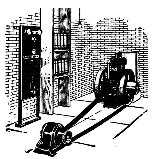 The Fairbanks Morse oil engine storage battery set
The tungsten lamp, requiring only one-third as much electric current as the carbon lamp, for the same amount of light, reduces the size (and the cost) of the storage battery in the same degree, thus bringing the storage battery within the means of the farmer. Some idea of the power that may be put into a small storage battery is to be had from the fact that a storage battery of only 6 volts pressure, such as is used in self-starters on automobiles, will turn a motor and crank a heavy six-cylinder engine; or it will run the automobile, without gasoline, for a mile or more with its own accumulated store of electric current.
The Low Voltage Battery
The 30-volt storage battery has become standard for small lighting plants, since the introduction of the tungsten lamp. Although the voltage of each separate cell of this battery registers 2.5 volts when fully charged, it falls to approximately 2 volts per cell immediately discharging begins. For this reason, it is customary to figure the working pressure of each cell at 2 volts. This means that a 30-volt battery should consist of at least 15 cells. Since, however, the voltage falls below 2 for each cell, as discharging proceeds, it is usual to include one additional cell for regulating purposes. Thus, the ordinary 30-volt storage battery consists of 16 cells, the last cell in the line remaining idle until the lamps begin to dim, when it is switched in by means of a simple arrangement of connections. This maintains a uniform pressure of 30 volts from the beginning to the end of the charge, at the lamp socket.
We saw in earlier chapters that the 110-volt[Pg 235] current is the most satisfactory, under all conditions, where the current is to be used for heating and small power, as well as light. But a storage battery of 110 volts would require at least 55 cells, which would make it too expensive for ordinary farm use. As a 30-volt current is just as satisfactory for electric light, this type has become established, in connection with the battery, and it is used for electric lighting only, as a general rule.
Batteries are rated first, as to voltage; second, as to their capacity in ampere hours—that is, the number of amperes that may be drawn from them in a given number of hours. Thus, a battery rated at 60 ampere hours would give 60 amperes, at 30 volts pressure, for one hour; 30 amperes for 2 hours; 15 amperes for 4 hours; 7˝ amperes for 8 hours; 3ľ amperes for 16 hours; etc., etc. In practice, a battery should not be discharged faster than its 8-hour rate. Thus, a 60-ampere hour battery should not be drawn on at a greater rate than 7˝ amperes per hour.
This 8-hour rate also determines the rate[Pg 236] at which a battery should be re-charged, once it is exhausted. Thus, this battery should be charged at the rate of 7˝ amperes for 8 hours, with another hour added to make up for losses that are bound to occur. A battery of 120-ampere hour capacity should be charged for 8 or 9 hours at the rate of 120 ÷ 8, or 15 amperes, etc.
To determine the size of battery necessary for any particular instance, it is necessary first to decide on the number of lamps required, and their capacity. Thirty-volt lamps are to be had in the market in sizes of 10, 15 and 20 watts; they yield respectively 8, 12, and 16 candlepower each. Of these the 20-watt lamp is the most satisfactory for the living rooms; lamps of 10 or 15 watts may be used for the halls, the bathroom and the bedrooms. At 30 volts pressure these lamps would require a current of the following density in amperes:
| Candle Power | 30-volt lamp | Amperes |
| 8 | 10 watts | 0.33 |
| 12 | 15 watts | 0.50 |
| 16 | 20 watts | 0.67 |
Let us assume, as an example, that Farmer Brown will use 20-watt lamps in his kitchen, dining room, and sitting room; and 10-watt lamps in the halls, bathroom, and bedrooms. His requirements may be figured either in lamp hours or in watt-hours. Since he is using two sizes of lamps, it will be simpler to figure his requirements in watt-hours. Thus:
| Room | Number of lamps | Size of lamps | Hours burned | Watt-hours | |
| Kitchen | 1 | 20 | 4 | 80 | |
| Dining room | 2 | 20 | 2 | 80 | |
| Sitting room | 3 | 20 | 4 | 240 | |
| (3) | Bedrooms | 1 (each) | 10 | 1 | 30 |
| Bathroom | 1 | 10 | 2 | 20 | |
| (2) | Halls | 1 (each) | 10 | 4 | 80 |
| Pantry | 1 | 10 | 1 | 10 | |
| Cellar | 1 | 10 | 1 | 10 | |
| ——— | |||||
| Total | 550 |
Since amperes equal watts divided by volts, the number of ampere hours required in this case each night would be 550 ÷ 30 = 18.3 ampere hours; or approximately 4˝ amperes per hour for 4 hours.
Say it is convenient to charge this battery every fourth day. This would require a battery [Pg 238]of 4 × 18.3 ampere hours, or 73.2 ampere hours. The nearest size on the market is the 80-ampere hour battery, which would be the one to use for this installation.
To charge this battery would require a dynamo capable of delivering 10 amperes of current for 9 hours. The generator should be of 45 volts pressure (allowing 2˝ volts in the generator for each 2 volts of battery) and the capacity of the generator would therefore be 450 watts. This would require a 1Ľ horsepower gasoline engine. At 1Ľ pints of gasoline for each horsepower, nine hours work of this engine would consume 14 pints of gasoline—or say 16 pints, or two gallons. At 12 cents a gallon for gasoline, lighting your house with this battery would cost 24 cents for four days, or 6 cents a day. Your city cousin, using commercial current, would pay 5˝ cents a day for the same amount of current at 10 cents a kilowatt-hour; or 8Ľ cents at a 15-cent rate. If the battery is charged by the farm gasoline engine at the same time it is doing its other work, the cost[Pg 239] would be still less, as the extra gasoline required would be small.
This figure does not take into account depreciation of battery and engine. The average farmer is too apt to overlook this factor in figuring the cost of machinery of all kinds, and for that reason is unprepared when the time comes to replace worn-out machinery. The dynamo and switchboard should last a lifetime with ordinary care, so there is no depreciation charge against them. The storage battery, a 30-volt, 80-ampere hour installation, should not cost in excess of $100; and, if it is necessary to buy a gasoline engine, a 1Ľ horsepower engine can be had for $50 or less according to the type. Storage batteries of the lead type are sold under a two-years' guarantee—which does not mean that their life is limited to that length of time. With good care they may last as long as 10 years; with poor care it may be necessary to throw them away at the end of a year. The engine should be serviceable for at least 10 years, with ordinary replacements; and the storage[Pg 240] battery may last from 6 to 10 years, with occasional renewal of parts. If it were necessary to duplicate both at the end of ten years, this would make a carrying charge of $1.25 a month for depreciation, which must be added to the cost of light.
Figuring by Lamp Hours
If all the lamps are to be of the same size—either ten, fifteen, or twenty watts, the light requirements of a farm house can be figured readily by lamp hours. In that event, the foregoing table would read as follows:
| Lamp hours | |
| Kitchen, 1 lamp, 4 hours | 4 |
| Sitting room, 3 lamps, 4 hours each | 12 |
| Dining room, 2 lamps, 2 hours each | 4 |
| Bedrooms, 3 lamps, 1 hour each | 3 |
| Halls, 2 lamps, 4 hours each | 8 |
| Bathroom, 1 lamp, 2 hours | 2 |
| Pantry and cellar, 2 lamps, 1 hour each | 2 |
To determine the ampere hours from this table, multiply the total number of lamp hours by the current in amperes required for each lamp. As 10, 15, and 20-watt tungsten lamps require .33, .50 and .67 amperes, respectively [Pg 241]at 30 volts pressure, the above requirements in ampere hours would be 12, 17˝, or 24 ampere hours, according to the size of lamp chosen. This gives the average current consumption for one night. If it is desired to charge the battery twice a week on the average, multiply the number of lamp hours by 4, to get the size of battery required.
The foregoing illustration is not intended to indicate average light requirements for farms, but is given merely to show how a farmer may figure his own requirements. In some instances, it will be necessary to install a battery of 120 or more ampere hours, whereas a battery of 40 or 60 ampere hours would be quite serviceable in other instances. It all depends on how much light you wish to use and are willing to pay for, because with a storage battery the cost of electric light is directly in proportion to the number of lights used.
As a general rule, a larger generator and engine are required for a larger battery—although it is possible to charge a large battery [Pg 242]with a small generator and engine by taking more time for the operation.
How to Charge a Storage Battery
Direct current only can be used for charging storage batteries. In the rare instance of alternating current only being available, it must be converted into direct current by any one of the many mechanical, chemical, or electrical devices on the market—that is, the alternating current must be straightened out, to flow always in one direction.
A shunt-wound dynamo must be used; else, when the voltage of the battery rises too high, it may "back up" and turn the dynamo as a motor, causing considerable damage. If a compound dynamo is already installed, or if it is desired to use such a machine for charging storage batteries, it can be done simply by disconnecting the series windings on the field coils, thus turning the machine into a shunt dynamo.
The voltage of the dynamo should be approximately 50 per cent above the working[Pg 243] pressure of the battery. For this reason 45-volt machines are usually used for 30 or 32-volt batteries. Higher voltages may be used, if convenient. Thus a 110-volt dynamo may be used to charge a single 2-volt cell if necessary, although it is not advisable.
Direction of Current
Electricity flows from the positive to the negative terminal. A charging current must be so connected that the negative wire of the dynamo is always connected to the negative terminal of the battery, and the positive wire to the positive terminal. As the polarity is always marked on the battery, there is little danger of making a mistake in this particular.
When the storage battery is charged, and one begins to use its accumulation of energy, the current comes out in the opposite direction from which it entered in charging. In this respect, a storage battery is like a clock spring, which is wound up in one direction, and unwinds itself in the other. With all storage battery outfits, an ammeter (or current measure) [Pg 244]is supplied with zero at the center. When the battery is being charged, the indicating needle points in one direction in proportion to the strength of the current flowing in; and when the battery is being discharged, the needle points in the opposite direction, in proportion to the strength of the current flowing out.
Sometimes one is at loss, in setting about to connect a battery and generator, to know which is the positive and which the negative wire of the generator. A very simple test is as follows:
Start the generator and bring it up to speed. Connect some form of resistance in "series" with the mains. A lamp in an ordinary lamp socket will do very well for this resistance. Dip the two ends of the wire (one coming from the generator, the other through the lamp) into a cup of water, in which a pinch of salt is dissolved. Bring them almost together and hold them there. Almost instantly, one wire will begin to turn bright, and give off bubbles. The wire which turns bright and gives off bubbles is the negative wire. The other is the positive.
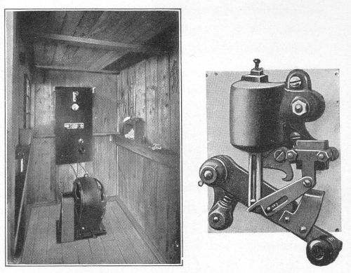 A rough-and-ready farm electric plant, supplying two
farms with light, heat and power; and a Ward Leonard-type
circuit-breaker for charging storage batteries
A rough-and-ready farm electric plant, supplying two
farms with light, heat and power; and a Ward Leonard-type
circuit-breaker for charging storage batteries
Care of Battery
Since specific directions are furnished with all storage batteries, it is not necessary to go into the details of their care here. Storage battery plants are usually shipped with all connections made, or plainly indicated. All that is necessary is to fill the batteries with the acid solution, according to directions, and start the engine. If the engine is fitted with a governor, and the switchboard is of the automatic type, all the care necessary in charging is to start the engine. In fact, many makes utilize the dynamo as a "self-starter" for the engine, so that all that is necessary to start charging is to throw a switch which starts the engine. When the battery is fully charged, the engine is stopped automatically.
The "electrolyte" or solution in which the plates of the lead battery are immersed, is sulphuric acid, diluted with water in the[Pg 246] proportion of one part of acid to five of water, by volume.
The specific gravity of ordinary commercial sulphuric acid is 1.835. Since its strength is apt to vary, however, it is best to mix the electrolyte with the aid of the hydrometer furnished with the battery. The hydrometer is a sealed glass tube, with a graduated scale somewhat resembling a thermometer. The height at which it floats in any given solution depends on the density of the solution. It should indicate approximately 1.15 for a storage battery electrolyte before charging. It should not be over 1.15—or 1,150 if your hydrometer reads in thousandths.
Only pure water should be used. Distilled water is the best, but fresh clean rain water is permissible. Never under any circumstances use hydrant water, as it contains impurities which will injure the battery, probably put it out of commission before its first charge.
Pour the acid into the water. Never under any circumstances pour the water into the acid, else an explosion may occur from the[Pg 247] heat developed. Mix the electrolyte in a stone crock, or glass container, stirring with a glass rod, and testing from time to time with a hydrometer. Let it stand until cool and then pour it into the battery jars, filling them to ˝ inch above the top of the plates.
Then begin charging. The first charge will probably take a longer time than subsequent charges. If the installation is of the automatic type, all that is necessary is to start the engine. If it is not of the automatic type, proceed as follows:
First be sure all connections are right. Then start the engine and bring the dynamo up to its rated speed. Adjust the voltage to the pressure specified. Then throw the switch connecting generator to battery. Watch the ammeter. It should register in amperes, one-eighth of the ampere-hour capacity of the battery, as already explained. If it registers too high, reduce the voltage of the generator slightly, by means of the field rheostat connected to the generator. This will also reduce the amperes flowing. If too low, raise the[Pg 248] voltage until the amperes register correctly. Continue the charging operation until the cells begin to give off gas freely; or until the specific gravity of the electrolyte, measured by the hydrometer, stands at 1.24. Your battery is now fully charged. Throw the switch over to the service line, and your accumulator is ready to furnish light if you turn on your lamps.
Occasionally add distilled water to the cells, to make up for evaporation. It is seldom necessary to add acid, as this does not evaporate. If the battery is kept fully charged, it will not freeze even when the thermometer is well below zero.
A storage battery should be installed as near the house as possible—in the house, if possible. Since its current capacity is small, transmission losses must be reduced to a minimum.
In wiring the house for storage battery service, the same rules apply as with standard voltage. Not more than 6 amperes should be used on any single branch circuit. With low voltage batteries (from 12 volts to 32 volts) it[Pg 249] is well to use No. 10 or No. 12 B. & S. gauge rubber-covered wire, instead of the usual No. 14 used with standard voltage. The extra expense will be only a few cents for each circuit, and precious volts will be saved in distribution of the current.
BATTERY CHARGING DEVICES
The automatic plant most desirable—How an automobile lighting and starting system works—How the same results can be achieved in house lighting, by means of automatic devices—Plants without automatic regulation—Care necessary—The use of heating devices on storage battery current—Portable batteries—An electricity "route"—Automobile power for lighting a few lamps.
The water-power electric plants described in preceding chapters are practically automatic in operation. This is very desirable, as such plants require the minimum of care. It is possible to attain this same end with a storage battery plant.
Automatic maintenance approaches a high degree of perfection in the electric starting and lighting device on a modern automobile. In this case, a small dynamo geared to the main shaft is running whenever the engine is running. It is always ready to "pump"[Pg 251] electricity into the storage battery when needed. An electric magnet, wound in a peculiar manner, automatically cuts off the charging current from the dynamo, when the battery is "full;" and the same magnet, or "regulator," permits the current to flow into the battery when needed. The principle is the same as in the familiar plumbing trap, which constantly maintains a given level of water in a tank, no matter how much water may be drawn from the tank. The result, in the case of the automobile battery, is that the battery is always kept fully charged; for no sooner does the "level" of electricity begin to drop (when used for starting or lighting) than the generator begins to charge. This is very desirable in more ways than one. In the first place, the energy of the battery is always the same; and in the second place, the mere fact that the battery is always kept fully charged gives it a long life.
The same result can be achieved in storage battery plants for house lighting, where the source of power is a gasoline or other engine[Pg 252] engaged normally in other work. Then your electric current becomes merely a by-product of some other operation.
Take a typical instance where such a plant would be feasible: Farmer Brown has a five horsepower gasoline engine—an ordinary farm engine for which he paid probably $75 or $100. Electric light furnished direct from such an engine would be intolerable because of its constant flickering. This five horsepower engine is installed in the milk room of the dairy, and is belted to a countershaft. This countershaft is belted to the vacuum pump for the milking machine, and to the separator, and to a water pump, any one of which may be thrown into service by means of a tight-and-loose pulley. This countershaft is also belted to a small dynamo, which runs whenever the engine is running. The milking machine, the separator, and the water pump require that the gasoline engine be run on the average three hours each day.
The dynamo is connected by wires to the house storage battery through a properly[Pg 253] designed switchboard. The "brains" of this switchboard is a little automatic device (called a regulator or a circuit breaker), which opens and shuts according to the amount of current stored in the battery and the strength of the current from the generator. When the battery is "full," this regulator is "open" and permits no current to flow. Then the dynamo is running idle, and the amount of power it absorbs from the gasoline engine is negligible. When the "level" of electricity in the battery falls, due to drawing current for light, the regulator is "shut," that is, the dynamo and battery are connected, and current flows into the battery.
These automatic instruments go still farther in their brainy work. They do not permit the dynamo to charge the battery when the voltage falls below a fixed point, due to the engine slowing down; neither do they permit the dynamo current to flow when the voltage gets too high due to sudden speeding up of the engine.
Necessarily, an instrument which will take[Pg 254] care of a battery in this way, is intricate in construction. That is not an argument against it however. A watch is intricate, but so long as we continue to wind it at stated intervals, it keeps time. So with this storage battery plant: so long as Farmer Brown starts his engine to do his farm chores every day, his by-product of electricity is stored automatically.
Such installations are not expensive. A storage battery capable of lighting 8 tungsten lamps, of 16 candlepower each, continuously for 8 hours (or fewer lamps for a longer time); a switchboard containing all the required regulating instruments; and a dynamo of suitable size, can be had for from $250 to $300. All that is necessary to put such a plant in operation, is to belt the dynamo to the gasoline engine so that it will run at proper speed; and to connect the wires from dynamo to switchboard, and thence to the house service. The dynamo required for the above plant delivers 10 amperes at 45 volts pressure, or 10 × 45 = 450 watts. A gasoline, gas, or oil[Pg 255] engine, or a windmill of 1˝ horsepower furnishes all the power needed. If the farmer uses his engine daily, or every other day, for other purposes, the cost of power will be practically negligible. With this system electric lights are available at any time day or night; and when the gasoline engine is in service daily for routine farm chores, the battery will never run low.
This system is especially desirable where one uses a windmill for power. The speed of the windmill is constantly fluctuating, so much so in fact that it could not be used for electric light without a storage battery. But when equipped with a regulator on the switchboard which permits the current to flow only when the battery needs it, and then only when the speed of the windmill is correct, the problem of turning wind power into electric light is solved.
If the farmer does not desire to go to the additional expense of automatic regulation, there are cheaper plants, requiring attention[Pg 256] for charging. These plants are identical with those described above, except they have no regulators. With these plants, when the battery runs low (as is indicated by dimming of the lights) it is necessary to start the engine, bring it up to speed, adjust the dynamo voltage to the proper pressure, and throw a switch to charge the battery. For such plants it is customary to run the engine to charge the battery twice a week. It is necessary to run the engine from 8 to 10 hours to fully charge the discharged battery. When the battery approaches full charge, the fact is evidenced by so-called "gassing" or giving off of bubbles. Another way to determine if the battery is fully charged is by means of the voltmeter, as the volts slowly rise to the proper point during the process of charging. A third way, and probably the most reliable is by the use of the hydrometer. The voltage of each cell when fully charged should be 2.5; it should never be discharged below 1.75 volts. Many storage battery electric light plants on the market are provided with[Pg 257] a simple and inexpensive circuit breaker, which automatically cuts off the current and stops the engine when the battery is charged. The current is then thrown from the dynamo to the house service by an automatic switch. If such a circuit breaker is not included, it is necessary to throw the switch by hand when charging is begun or ended.
Since the principal item of first cost, as well as depreciation, in a storage battery electric light plant is the storage battery itself, the smallest battery commensurate with needs is selected. Since the amount of current stored by these batteries is relatively small, electric irons and heating devices such as may be used freely on a direct-connected plant without a battery, are rather expensive luxuries. For instance, an electric iron drawing 400 watts an hour while in use, requires as much energy as 20 tungsten lamps of 16 candlepower each burning for the same length of time. Its rate of current consumption would be over 13 amperes, at 30 volts; which would require a larger battery than[Pg 258] needed for light in the average farm home.
The use to which electricity from a storage battery is put, however, is wholly a matter of expense involved; and if one is willing to pay for these rather expensive luxuries, there is no reason why he should not have them. Heating, in any form, by electricity, requires a large amount of current proportionally. As a matter of fact, there is less heat to be had in thermal units from a horsepower-hour of electricity than from three ounces of coal. When one is generating current from water-power, or even direct from gasoline or oil, this is not an argument against electric heating devices. But it becomes a very serious consideration when one is installing a storage battery as the source of current, because of the high initial cost, and depreciation of such a battery.
Farmers who limit the use of their storage battery plants to lighting will get the best service.
Portable Batteries
Abroad it is becoming quite common for power companies to deliver storage batteries fully charged, and call for them when discharged. Without a stretch of the imagination, we can imagine an ingenious farmer possessing a water-power electric plant building up a thriving business among his less fortunate neighbors, with an "electricity" route. It could be made quite as paying as a milk route.
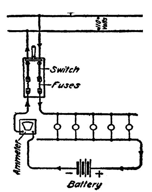 Connections for charging storage batteries on 110-volt
mains
Connections for charging storage batteries on 110-volt
mains
Many communities have water or steam power at a distance too great to transmit 110-volt current by wire economically; and because of lack of expert supervision, they do not care to risk using current at a pressure of 500 volts or higher, because of its danger to human life.
In such a case it would be quite feasible for families to wire their houses, and carry their[Pg 260] batteries to the generating plant two or three times a week to be charged. There are a number of portable batteries on the market suitable for such service, at voltages ranging from 6 to 32 volts. The best results would be obtained by having two batteries, leaving one to be charged while the other was in use; and if the generating station was located at the creamery or feed mill, where the farmer calls regularly, the trouble would be reduced to a minimum.
Such a battery would necessarily be small, and of the sealed type, similar to those used in automobiles. It could be used merely for reading lamps—or it could be used for general lighting, according to the expense the farmer is willing to incur for batteries.
An ordinary storage battery used in automobile ignition and lighting systems is of the 6-volt, 60-ampere type, called in trade a "6-60." Lamps can be had for these batteries ranging in sizes from 2 candlepower to 25 candlepower. A lamp of 15 candlepower, drawing 2˝ amperes, is used for automobile[Pg 261] headlights, and, as any one knows after an experience of meeting a headlight on a dark road, they give a great deal of light. A "6-60" battery keeps one of these lamps running for 24 hours, or two lamps running 12 hours. A minimum of wiring would be required to install such a battery for the reading lights in the sitting room, and for a hanging light in the dining room. The customary gates for charging these batteries in a large city is 10 cents; but in a country plant it could be made less.
To charge such a battery on a 110-volt direct current, it is necessary to install some means of limiting the amount of current, or in other words, the charging rate. This charging rate, for 8 hours should be, as we have seen, one-eighth of the ampere-hour capacity of the battery. Thus a "6-60" battery would require a 7˝ ampere current.
Connecting two such batteries in "series" (that is, the negative pole of one battery to the positive pole of the second) would make a 12-volt battery. Ten or twelve such batteries[Pg 262] could be connected in "series," and a 110-volt direct current generator would charge them in 8 hours at a 7˝ ampere rate.
The diagram on page 259 shows the connections for charging on a 110-volt circuit.
An ordinary 16-candlepower carbon lamp is of 220 ohms resistance, and (by Ohm's Law, C equals E divided by R) permits ˝ ampere of current to flow. By connecting 15 such lamps across the mains, in parallel, the required 7˝ amperes of current would be flowing from the generator through the lamps, and back again. Connect the battery in "series" at any point on either of the two mains, between the lamps and the generator, being careful to connect the positive end to the positive pole of the battery, and vice versa.
Lamps are the cheapest form of resistance; but in case they are not available, any other form of resistance can be used. Iron wire wound in spirals can be used, or any of the many makes of special resistance wire on the market. First it is necessary to determine the amount of resistance required.
We have just seen that the charging rate of a 60-ampere hour battery is 7˝ amperes. Applying Ohm's Law here, we find that ohms resistance equals volts divided by amperes, or R = 110/7.5 = 14.67 ohms. With a 220-volt current, the ohms resistance required in series with the storage battery of this size would be 29.33 ohms.
Automobile Power for Lighting
There are many ingenious ways by which an automobile may be utilized to furnish electric light for the home. The simplest is to run wires direct from the storage battery of the self-starting system, to the house or barn, in such a way that the current may be used for reading lamps in the sitting room. By a judicious use of the current in this way, the normal operation of the automobile in the daytime will keep the battery charged for use of the night lamps, and if care is used, such a plan should not affect the life of the battery. Care should be used also, in this regard, not to discharge the battery too low[Pg 264] to prevent its utilizing its function of starting the car when it was desired to use the car. However, if the battery were discharged below its starting capacity, by any peradventure, the car could be started by the old-fashioned cranking method.
Using an automobile lighting system for house lighting implies that the car be stored in a garage near the house or barn; as this battery is too low in voltage to permit transmitting the current any distance. One hundred feet, with liberal sized transmission wires is probably the limit.
That such a system is feasible is amply proved by an occurrence recently reported in the daily papers. A doctor summoned to a remote farm house found that an immediate operation was necessary to save the patient's life. There was no light available, except a small kerosene lamp which was worse than nothing. The surgeon took a headlight off his car, strung a pair of wires through a window, and instantly had at his command a light of the necessary intensity.
Another manner in which an automobile engine may be used for house lighting is to let it serve as the charging power of a separate storage battery. The engine can be belted to the generator, in such a case, by means of the fly wheel. Or a form of friction drive can be devised, by means of which the rear wheels (jacked up off the floor) may supply the necessary motive power. In such a case it would be necessary to make allowance for the differential in the rear axle, so that the power developed by the engine would be delivered to the friction drive.
The following pages contain advertisements of Macmillan books by the same author or on related subjects.
WATER POWER ENGINEERS
DESIGNERS AND MANUFACTURERS
HUNT
SUPERIOR QUALITY
Complete equipments for developing water powers including:—Water Wheels, Flumes, Governors, Supply Pipes, Gates, Hoists, Valves, Screens, Gears, Pulleys, Clutches, Bearings, Shafting, etc.
Three types of water power developing wheels, ranged to meet every condition.
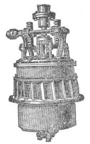
Div. No. 1—Turbine Water Wheels for large powers and large quantities of water.
Div. No. 2—Rim Leverage Wheels for small powers and very limited quantities of water.
Div. No. 3—Small Water Motors for minimum water supplies under high heads.
Send for special catalogues and Water Power Blanks to fill in for estimates on suitable type of Water Wheel for developing your water power to best advantage.
RODNEY HUNT MACHINE COMPANY
60 MILL STREET
ORANGE, MASSACHUSETTS, U.S.A.
The Farmer of Tomorrow
Cloth, 12mo, $1.50
"A crisp, entertaining, and instructive discussion of the conditions which have brought about the present agricultural problem in America."—Countryside Magazine.
"The book is interestingly written and full of many vital discussions."—Annals of the American Academy of Political and Social Science.
"A popular consideration of the fundamental factors affecting the business of farming."—Pacific Rural Press.
"The growing, popular question of farming analyzed from all angles, with many helpful suggestions."—Leslie's Weekly.
"Any person of intelligence, alive to the present and future welfare of his country will find 'The Farmer of Tomorrow,' a book of absorbing character."—Times-Star.
THE MACMILLAN COMPANY
Publishers
64-66 Fifth Avenue
New York
Coöperation in Agriculture
By G. HAROLD POWELL
Cloth, 12mo, $1.50
"The author has a broad outlook and never fails to suggest that the economic advantages of coöperation may frequently be quite subordinate to the general social and community interests which are fostered through a common undertaking. He writes with the genuine interest of a man having experience and faith in that of which he speaks."—Political Science Quarterly.
"A volume which explains in a lucid way the features of the existing system and the measures taken by farmers to protect their interests."—Journal of the Royal Statistical Society.
"Mr. Powell has not attempted to cover the entire field of agricultural coöperation, but has confined himself to its more important phases. His work shows a grasp of the issues involved and a ripeness of conclusion that comes only from actual contact with the practical side of coöperation."—American Economic Review.
"The book is decidedly worth while."—Farm Life and Agriculture.
THE MACMILLAN COMPANY
Publishers
64-66 Fifth Avenue
New York
RURAL SCIENCE SERIES
Edited by L. H. BAILEY
Each volume illustrated. Cloth, 12mo.
A series of practical books for farmers and gardeners, sold as a set or separately. Each one is the work of a competent specialist, and is suitable for consultation alike by the amateur or professional tiller of the soil, the scientist or the student. Illustrations of marked beauty are freely used, and the books are clearly printed and well bound.
| ON SELECTION OF LAND, ETC. | |
| Isaac P. Roberts' The Farmstead | $1 50 |
| T. F. Hunt's How to Choose a Farm | 1 75 |
| E. S. Cheyney and J. P. Wentling's The Farm Woodlot | 1 50 |
| Glenn W. Herrick's Insects Injurious to the Household | 1 75 |
| ON TILLAGE, ETC. | |
| F. H. King's The Soil | 1 50 |
| Isaac P. Roberts' The Fertility of the Land | 1 50 |
| F. H. King's Irrigation and Drainage | 1 50 |
| Edward B. Voorhees' Fertilizers | 1 25 |
| Edward B. Voorhees' Forage Crops | 1 50 |
| J. A. Widtsoe's Dry Farming | 1 50 |
| L. H. Bailey's Principles of Agriculture | 1 25 |
| S. M. Tracy's Forage Crops for the South | 1 50 |
| ON PLANT DISEASES, ETC. | |
| E. C. Lodeman's The Spraying of Plants | 1 25 |
| ON GARDEN-MAKING | |
| L. H. Bailey's Garden-Making | 1 50 |
| L. H. Bailey's Vegetable-Gardening | 1 50 |
| L. H. Bailey's Forcing Book | 1 25 |
| L. H. Bailey's Plant Breeding | 2 00 |
| ON FRUIT-GROWING, ETC. | |
| L. H. Bailey's Nursery Book | 1 50 |
| L. H. Bailey's Fruit-Growing (New Edition) | 1 75 |
| L. H. Bailey's The Pruning Book | 1 50 |
| F. W. Card's Bush Fruits | 1 50 |
| W. Paddock & O. B. Whipple's Fruit-Growing in Arid Regions | 1 50 |
| J. E. Coit's Citrus Fruits | Prepar |
| ON THE CARE OF LIVE-STOCK | |
| Nelson S. Mayo's The Diseases of Animals | 1 50 |
| W. H. Jordan's The Feeding of Animals | 1 50 |
| I. P. Roberts' The Horse | 1 25 |
| M. W. Harper's Breaking and Training of Horses | 1 75 |
| George C. Watson's Farm Poultry. New edition | 1 50 |
| John A. Craig's Sheep Farming | 1 50 |
| ON DAIRY WORK, FARM CHEMISTRY, ETC. | |
| Henry H. Wing's Milk and Its Products. New edition | 1 50 |
| J. G. Lipman's Bacteria and Country Life | 1 50 |
| ON ECONOMICS AND ORGANIZATION | |
| William A. McKeever's Farm Boys and Girls | 1 50 |
| I. P. Roberts' The Farmer's Business Handbook | 1 25 |
| George T. Fairchild's Rural Wealth and Welfare | 1 25 |
| H. N. Ogden's Rural Hygiene | 1 50 |
| J. Green's Law for the American Farmer | 1 50 |
| G. H. Powell's Coöperation in Agriculture | 1 50 |
THE MACMILLAN COMPANY
PUBLISHERS
64-66 Fifth Avenue
NEW YORK
RURAL TEXT-BOOK SERIES
Edited by L. H. BAILEY
Each volume illustrated. Cloth, 12mo.
While the RURAL SCIENCE SERIES is designed primarily for popular reading and for general use, this related new series is designed for classroom work and for special use in consultation and reference. The RURAL TEXT-BOOK SERIES is planned to cover eventually the entire range of public school and college texts.
| Duggar, B. M. | |
| Physiology of Plant Production | $1 60 |
| Duggar, John Frederick | |
| Southern Field Crops | 1 75 |
| Gay, C. Warren | |
| Principles and Practice of Judging Live-Stock | 1 50 |
| Harper, M. W. | |
| Animal Husbandry for Schools | 1 40 |
| Hitchcock, A. S. | |
| Grasses | 1 50 |
| Livingston, George | |
| Field Crop Production | 1 40 |
| Lyon, T. L. and Fippin, E. O. | |
| Principles of Soil Management | 1 75 |
| Mann, A. R. | |
| Beginnings in Agriculture | 75 |
| Montgomery, G. F. | |
| Corn Crops | 1 60 |
| Piper, Charles V. | |
| Forage Plants and Their Culture | 1 75 |
| Warren, G. F. | |
| Elements of Agriculture | 1 10 |
| Warren, G. F. | |
| Farm Management | 1 75 |
| Wheeler, H. J. | |
| Manures and Fertilizers | 1 60 |
| Widtsoe, John A. | |
| Principles of Irrigation Practice | 1 75 |
THE MACMILLAN COMPANY
PUBLISHERS
64-66 Fifth Avenue
NEW YORK
The Rural Outlook Set
By L. H. BAILEY
Four Volumes. Each, cloth, 12mo. Uniform binding, attractively boxed. $5.00 per set; carriage extra. Each volume also sold separately.
In this set are included three of Professor Bailey's most popular books as well as a hitherto unpublished one,—"The Country-Life Movement." The long and persistent demand for a uniform edition of these little classics is answered with the publication of this attractive series.
The Country Life Movement
Cloth, 12mo, 220 pages, $1.25 postage extra
This hitherto unpublished volume deals with the present movement for the redirection of rural civilization, discussing the real country-life problem as distinguished from the city problem, known as the back-to-the-land movement.
The Outlook to Nature (New and Revised Edition)
Cloth, 12mo, 195 pages, $1.25 postage extra
In this alive and bracing book, full of suggestions and encouragement, Professor Bailey argues the importance of contact with nature, a sympathetic attitude toward which "means greater efficiency, hopefulness, and repose."
The State and the Farmer (New Edition)
Cloth, 12mo, $1.25 postage extra
It is the relation of the farmer to the government that Professor Bailey here discusses in its varying aspects. He deals specifically with the change in agricultural methods, in the shifting of the geographical centers of farming in the United States, and in the growth of agricultural institutions.
The Nature Study Idea (New Edition)
Cloth, 12mo, $1.25 postage extra
"It would be well," the critic of The Tribune Farmer once wrote, "if 'The Nature Study Idea' were in the hands of every person who favors nature study in the public schools, of every one who is opposed to it, and most important, of every one who teaches it or thinks he does." It has been Professor Bailey's purpose to interpret the new school movement to put the young into relation and sympathy with nature,—a purpose which he has admirably accomplished.
THE MACMILLAN COMPANY
PUBLISHERS
64-66 Fifth Avenue
NEW YORK
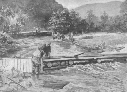 Farm labor and materials built this crib and stone
dam
Farm labor and materials built this crib and stone
dam
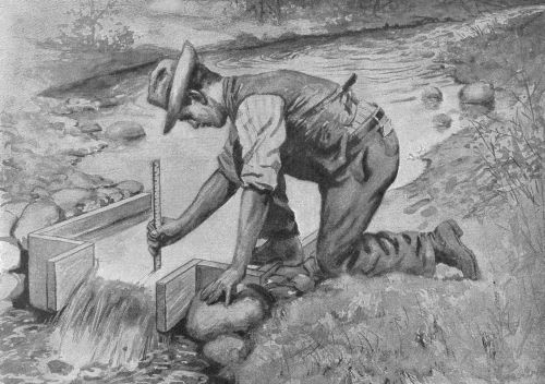 Measuring a small stream with a weir
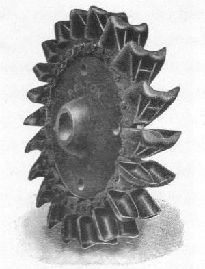
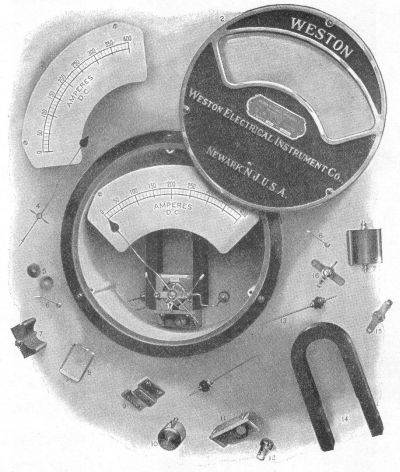 Details of voltmeter or ammeter
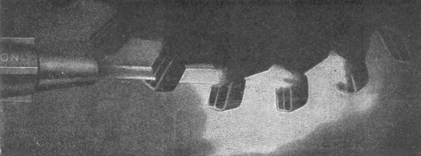 Instantaneous photograph of high-pressure water jet
being quenched by buckets of a tangential wheel
Instantaneous photograph of high-pressure water jet
being quenched by buckets of a tangential wheel